|
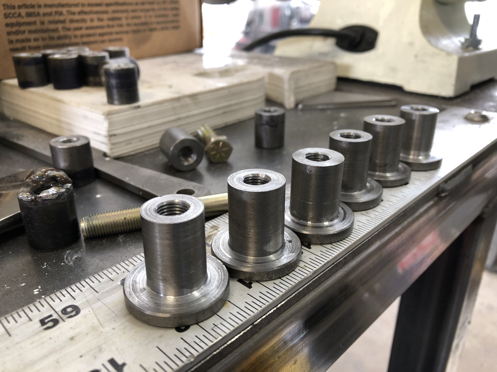
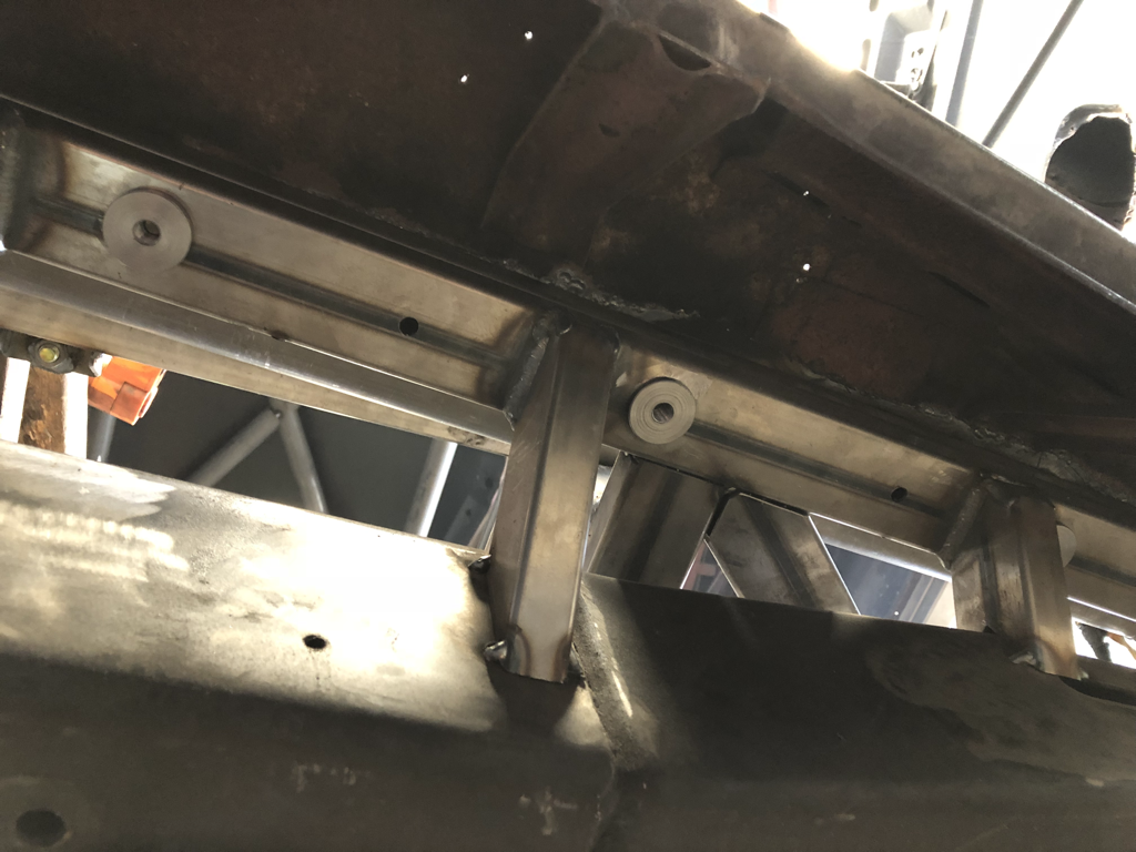
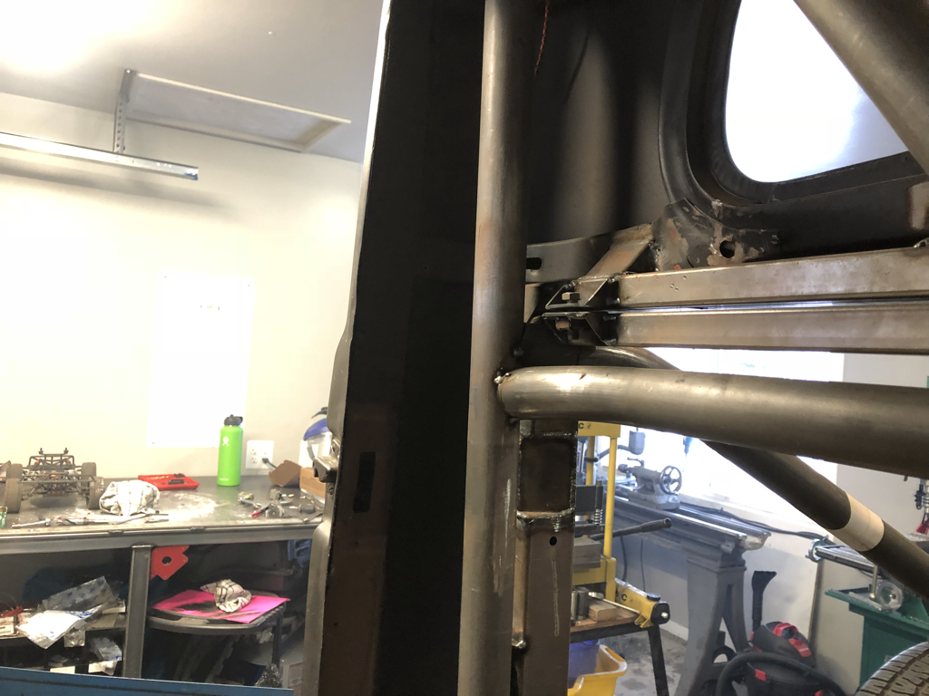
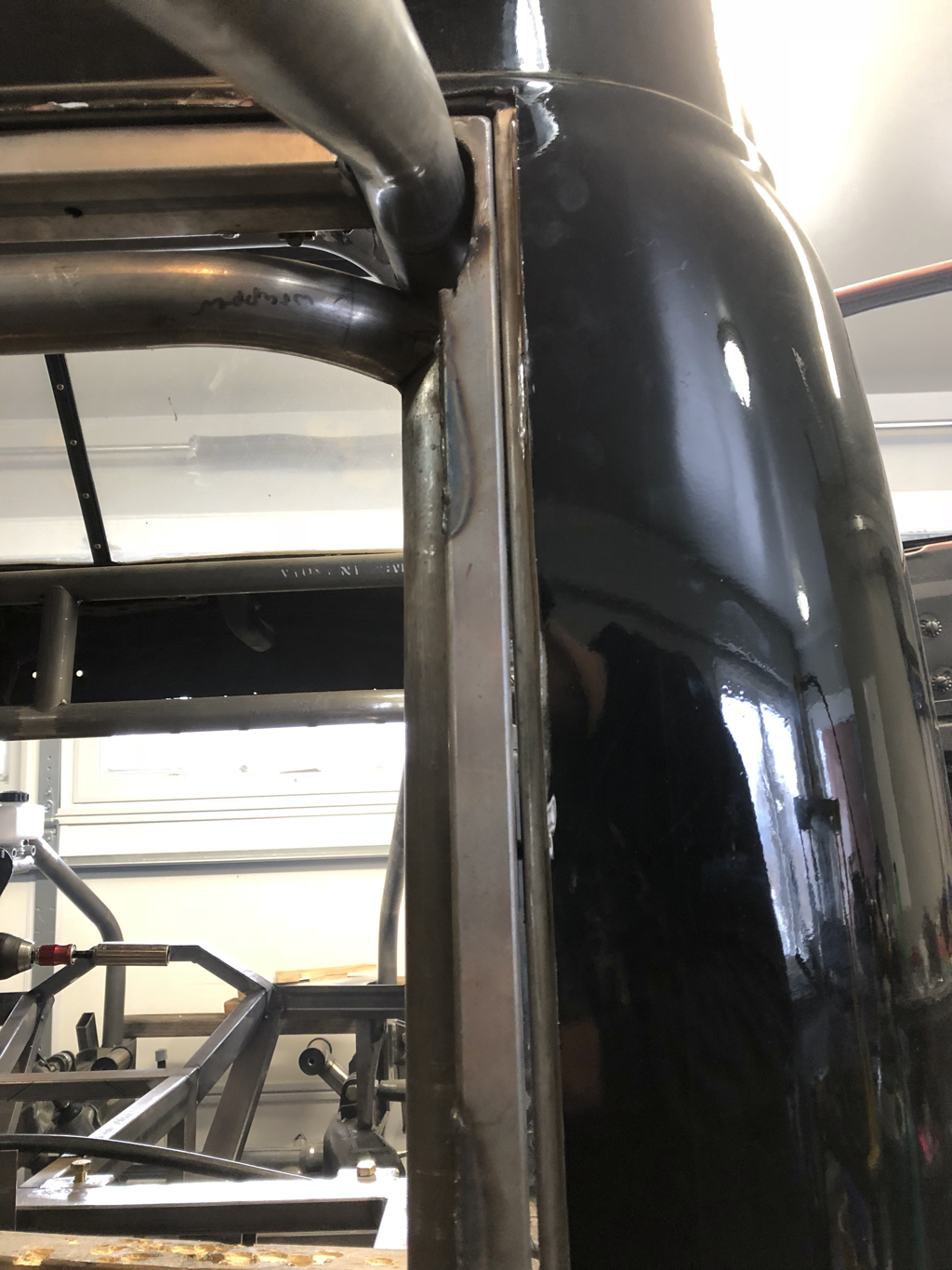
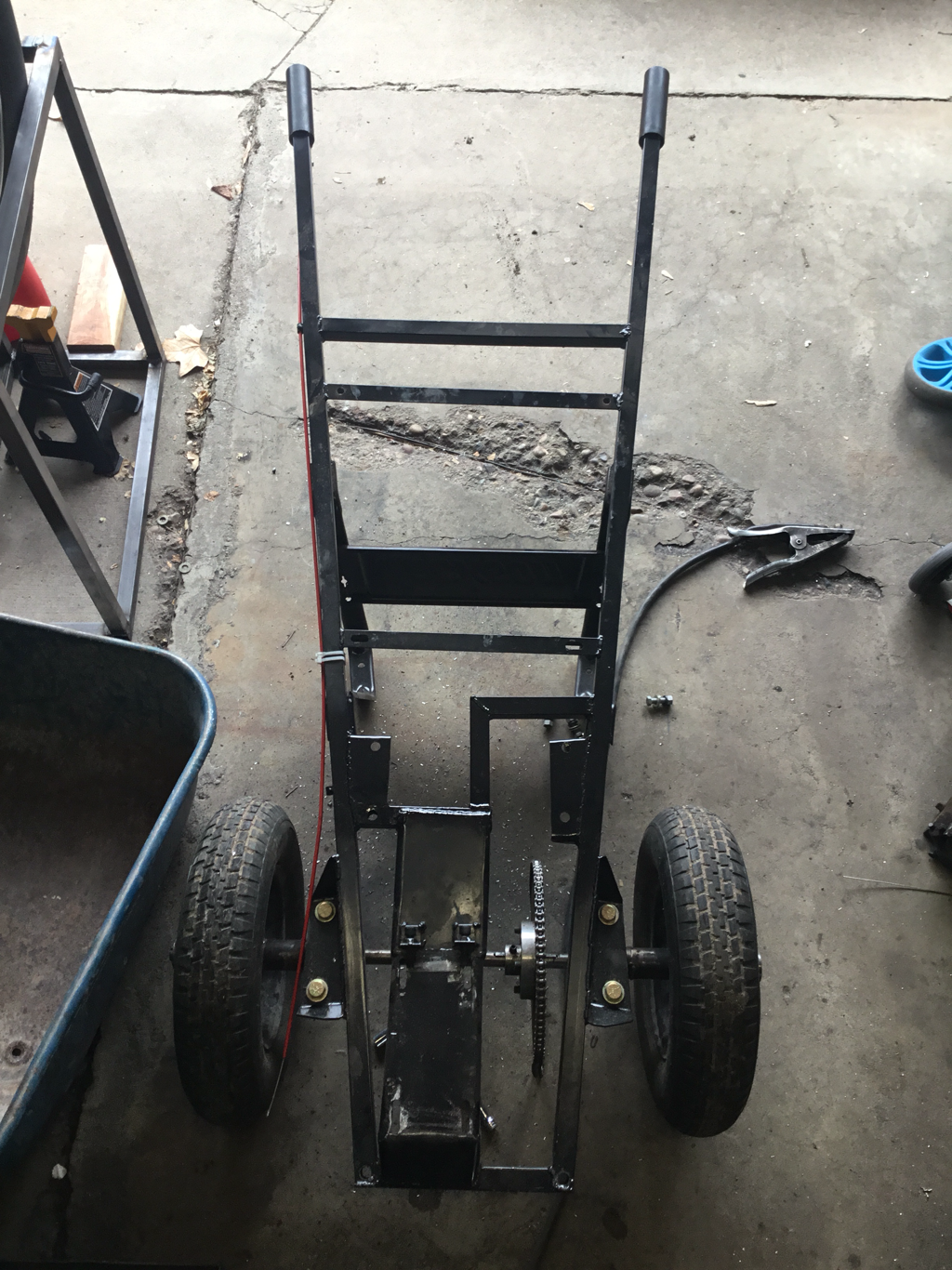
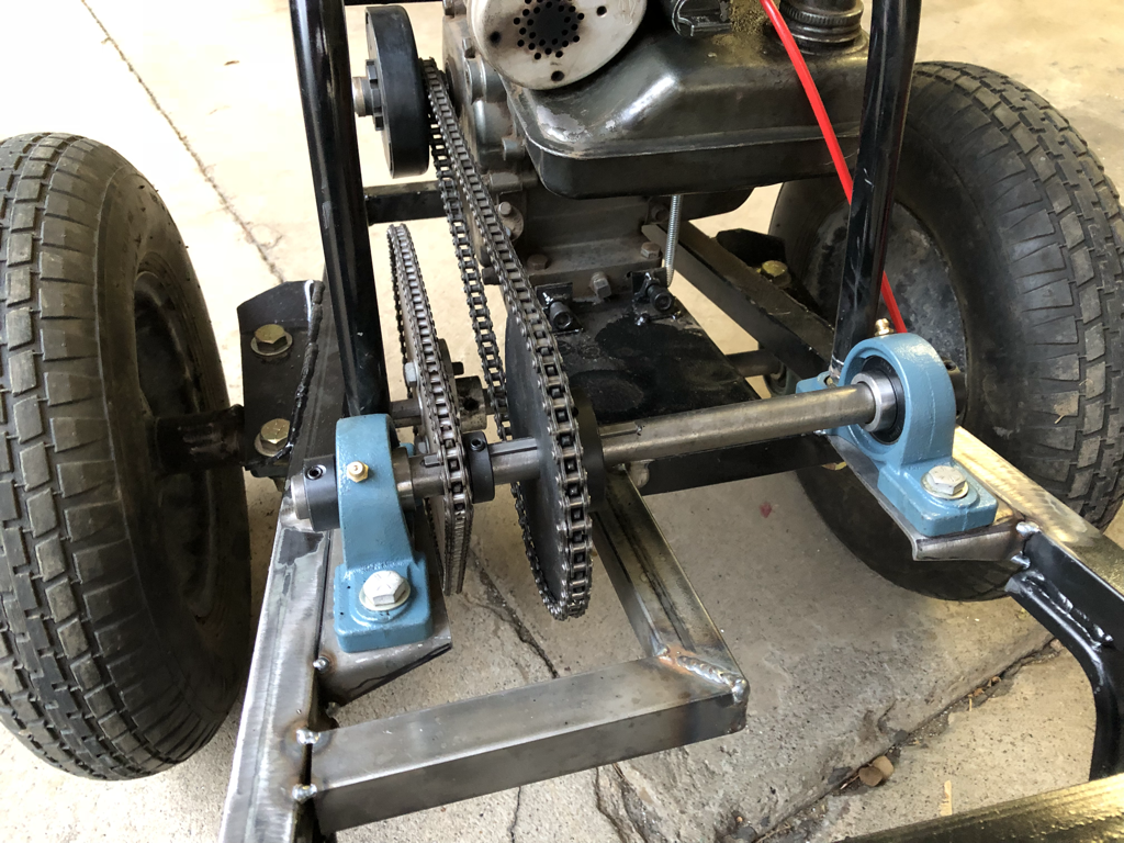
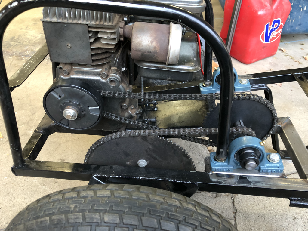
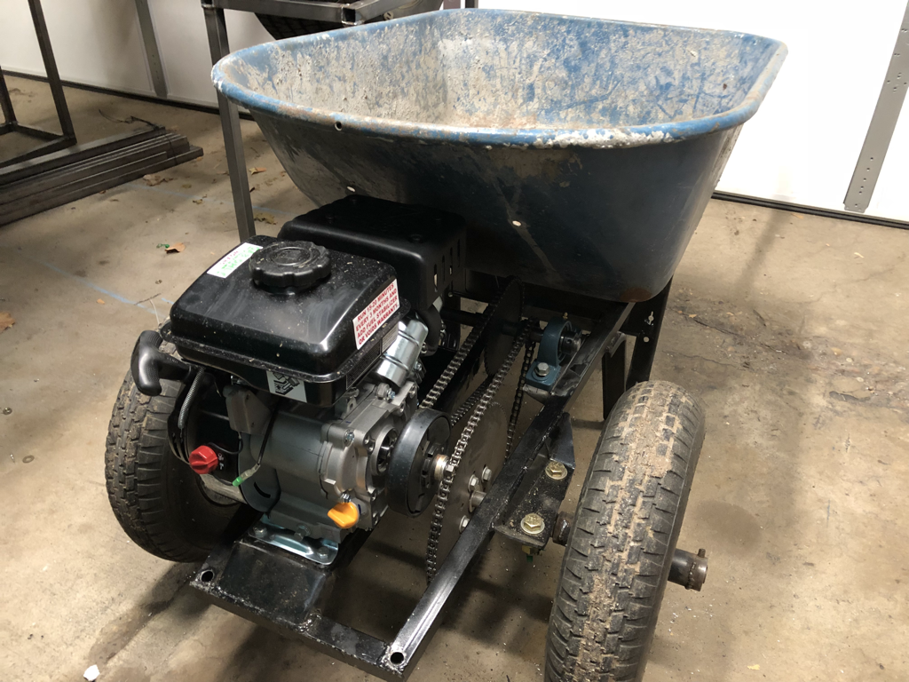
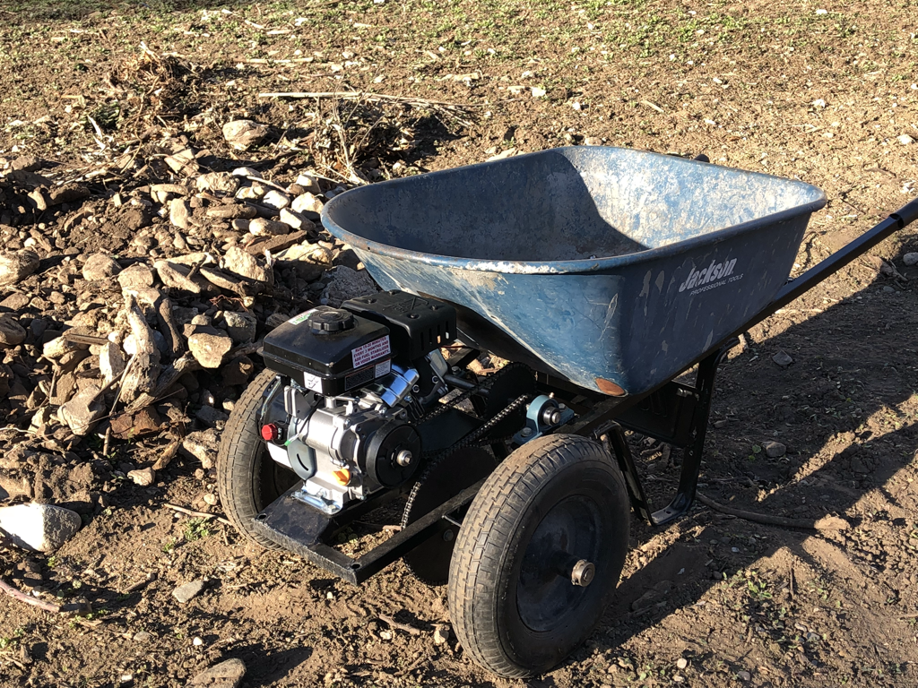
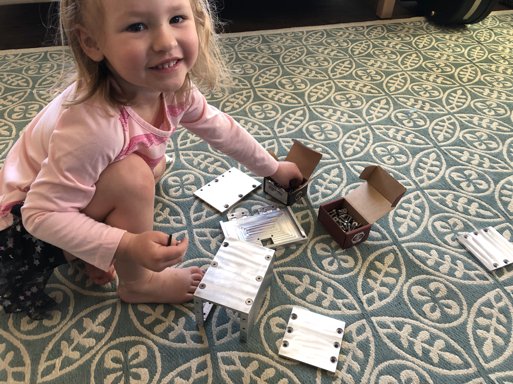
Im going to start off with Drift Stude updates even though they technically didnt’ happen until the end of Feb... starting with the above picture. After thinking about it for a while I decided to remake the bottom threaded parts of my body mounts mentioned a post or two ago. The re-make is purely a way to weld them on the bottom side of the truck a little easier while at the same time not risking welding into any of the threaded part. This is the solution I came up wth. I managed to get some time lapse shots of the revised body mount design coming to life on the lathe. Making 6 of these took about 1.5 hrs total. This is where they ended up. This give a lot better chance of doing a nice weld and will probably be a little stronger too. The top pass through bushing will remain unchanged. After tacking them in place on the under side I moved to finish welding in the top side of the body mounts. This meant re drilling to clean up the hole as my welds were a little fat. And then smoothing them out a little with the grinder. last up on the body mount front was to tack in the rest of the body mounts using my first design in the places where they could still be used. And wouldn’t interfere when it came time to pull the body off. One of which is seen here. Next up is to prepare to weld the body to the square tubing channel that stays with it when the body is removed. this meant trimming the back sheet metal back a bit so i could get a. Good weld on the square tubing and sheet metal. For now I plan on ding tack welds about every 2 or 3 inches just go get it solid enough to lift off without shifting. Trimming went well, though I still have a bit of work to do before welding on the top sheet metal part. I need to bend the metal ever so slightly to contact the square tubing behind it before welding. To complicate it a bit there is belt line in the rear of the cab right at that point. This was poor planning on my part long ago when I cut this out, but it is totally fixable and I will have to bend the metal there in a uniform bead pattern in order to make it look decent. Also, already the stands I made to get the stude up off the ground are paying off. I would have been bending over for hours doing the mounts and body trimming, Now it is comfortably at standing height. And that is all the drift stude work I got done in Feb, but that wasn’t the end of my garage tinkering. Next up wheel barrow updates: FAfter completing the wheelbarrow a few months ago i mentioned that I would probably need to gear it down a bit. Feb was the time to get that done as it looked like spring was going to be here early and the wheelbarrow is going to play a very important role in this years yard work. In the picture above you will notice that i cut out a portion of the upper crossmember going under the motor mount. Then it was extended to the rear and then reconnected to the other side. I also added two new pillow block bearing mount brackets. All of this is so I can install another keyed shaft with two more sprockets on it. Here is the end results with sprockets and bearings installed. You will also see that this required a flip of the clutch so that its sprocket is closer to the motor and allowed more room for the dual chain setup. Before I ordered the sprockets I had to runs some calculations to get everything right. I knew that the clutch shoes were designed to be fully engaged with no slippage at 2000 rpm. And that the motor had a max rpm at around 3000. I also knew that I already had an 80 tooth sprocket and an 11 tooth sprocket. And the wheel diameter was 16 inches. I also knew that I wanted the clutch to be fulling engaged by the time the speed was up to a walking pace, which i decided would be 3.5 mph. Admittedly this is a slightly fast walking pace. Armed with my known figures I plugged all this into various sprocket rpm calculators, and took those sprocket rpms and plugged those rpm speeds into wheel speed calculators. The result was that I needed a 48 tooth sprocket and a 13 tooth sprocket on my knew jack shaft in order to get the lower speeds I desired. And upon ordering the sprockets(i opted for some with keyways already cut). It was determined that they only had a 44 tooth sprocket in stock, which rose my walking speed at 200rpm motor speed by a fraction of an MPH. The order was placed and you can see how it all fit together. another side shot of the new setup. You will also notice that in order to keep my same engine cover i had to shorten the back legs of that frame and reeled the captive nuts and use the bolts for the pillow blocks to hold that down. You will see next that ultimately this changed. When it was time to fire it up and run it around to test the gearing I couldn’t get the motor to idle at all, and then I couldn’t get the motor to run at all. After some trial and error I was left with the assumption that the magneto or distributor... not sure what it really has had failed and rather than spend time trying to find another one, I opted to buy a brand new harbor freight 3hp unit. It bolted up in the exact same place, though I did have to add some links back into the chain as the motor shaft was slightly more forward. I also had to re-route the throttle cable, but overall the motor swap was easy. The engine cover and frame I had made did not fit this new motor as it sat slightly taller. But the good news is that the gas tank is in a much better spot and after some tests I realized it doesn’t really need a cover... or at least as far as i can tell when dumping rocks and dirt. Concrete may be a little different but that has yet to be seen. one more picture of the wheelbarrow before some yard work mid feb. it was 60 degrees this day which is way out of wack for feb in norther Utah. You can even see weeds sprouting in the dirt. I am happy to report that we got back to winter the week after this photo with two big storms that each dumped almost a foot at my house. I made a little video to show a few things: First the hill on the side of my house which is the whole reason for making this thing. Two, that when you dump a load it goes right over the motor without issue. Three that the motor doesn’t die when a load is dump... as long as it is done quickly enough. And fourth that it can do burnouts now. It can do dirt burnouts with a full 150lb load, and it’ll do cement/asphalt burnouts with a 60lb load. Anything more than that on a hard surface and it over powers the clutch a little. I think the wheelbarrow is near perfect now for mine, but my little brother has requested one for himself and we will refine a couple little things. More on motorized wheelbarrow #2 later. now onto the aluminum box. The box is done of course and my daughter loves it. She had fun putting it together for the first time, and took little parts off it for a day or two after, but now it is doing hard duty storing little trinkets, and the Allen key for the screws. Here is the last part of the build video. I did not get any footage of making the little latch mechanism, as it was 2:00 am when I got around to it and i was dead tired. But there is a little bit in the video showing exacltly how it latches. I really had a great time building this little box, in reality it took about 18-20 hrs to complete, which is way overkill for a little box, but hey it will most likely outlast me, and my daughter.
And with that consider yourself caught up for Feb. I am planning on more stude work in march and hopefully the body will be off by the time I post about it. ,I am also starting some other smaller side projects which I am pumped about but more on those later.
0 Comments
Leave a Reply. |
Download the
following Designs used in this build: Archives
February 2018
|
