|
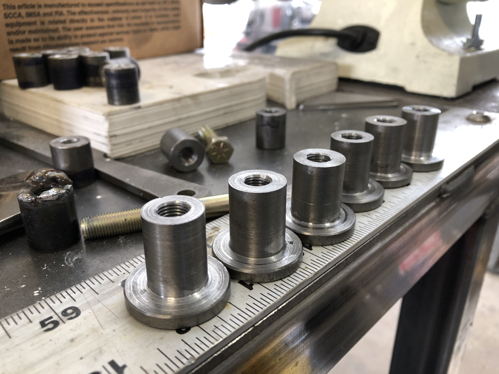
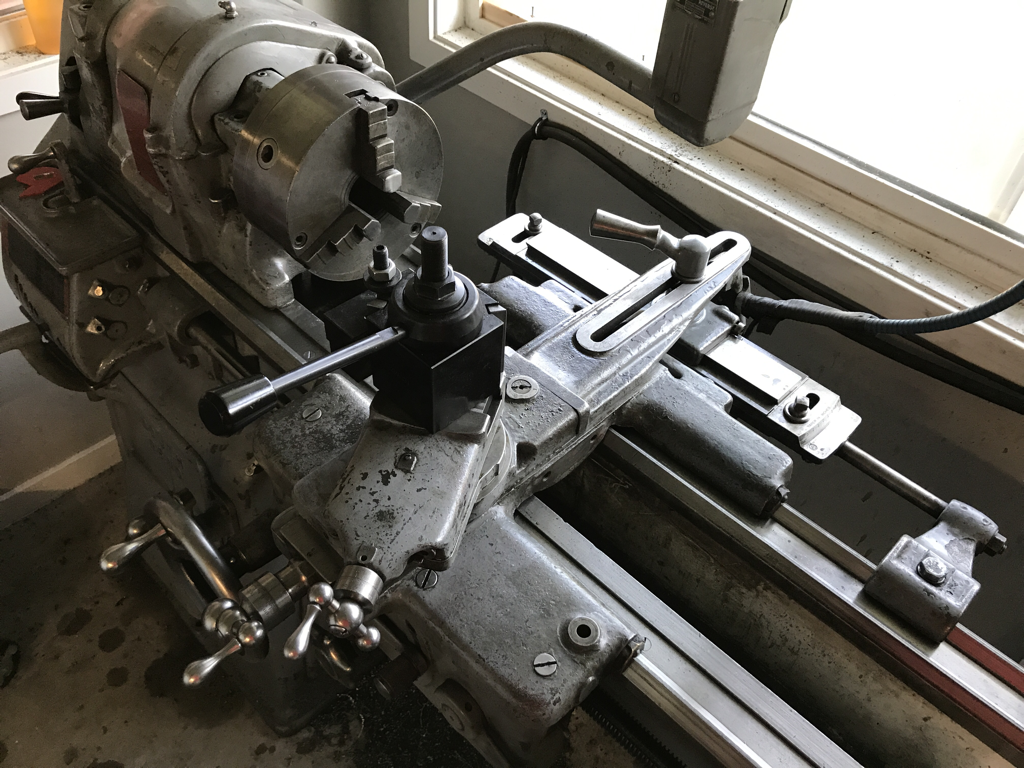
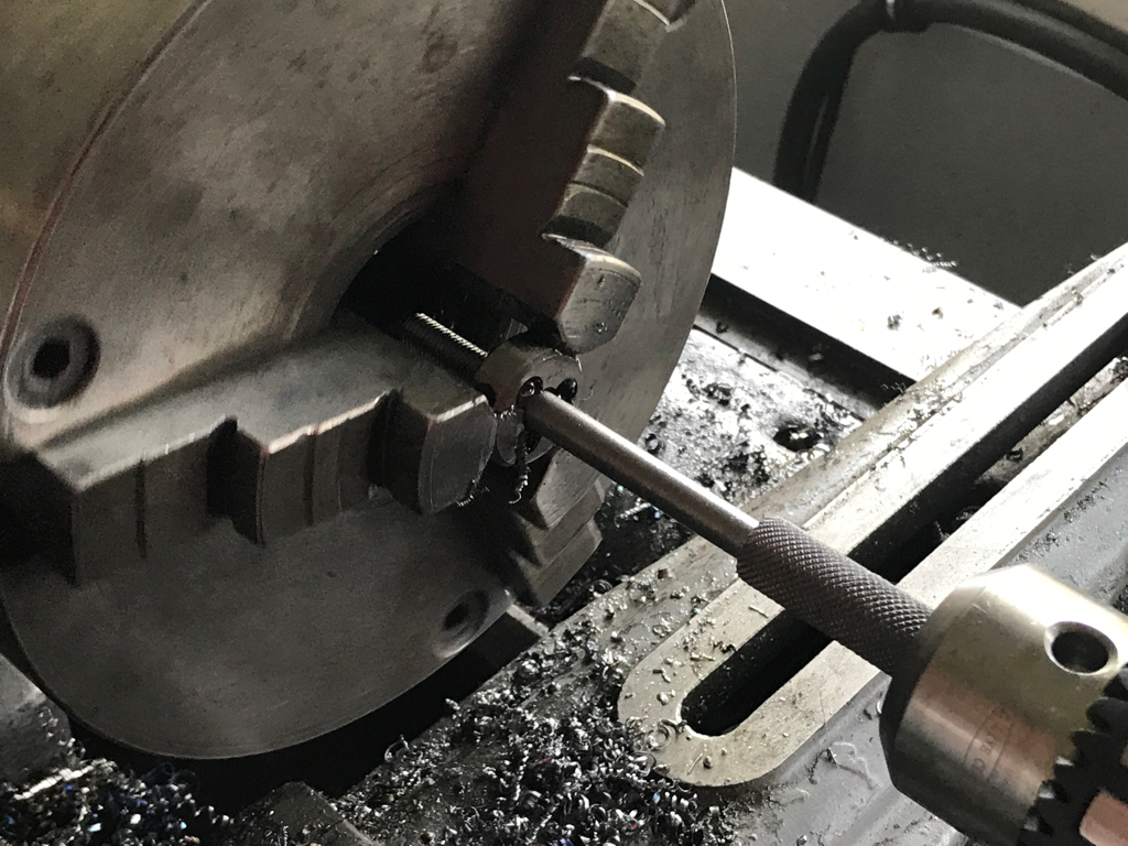
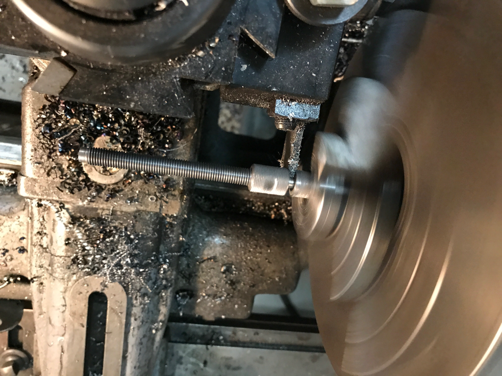
Im going to start off with Drift Stude updates even though they technically didnt’ happen until the end of Feb... starting with the above picture. After thinking about it for a while I decided to remake the bottom threaded parts of my body mounts mentioned a post or two ago. The re-make is purely a way to weld them on the bottom side of the truck a little easier while at the same time not risking welding into any of the threaded part. This is the solution I came up wth. I managed to get some time lapse shots of the revised body mount design coming to life on the lathe. Making 6 of these took about 1.5 hrs total.
0 Comments
January was a fairly productive month... it all started with some good old fashioned christmas money, which I promptly spent on a new garage door opener as the old one gave up the ghost a few months back, and I was getting really tired of opening the garage manually. I even did a couple of upgrades compared to the old one and got a WiFi enabled one along with key pad entry. Sadly I did not get any videos or pictures of it, though you can see traces of the install in the video below. starting in early December I decided it to cross off one of my major purchase goals, a dirtbike for my daughter. Every once in a while I take her down to our local motorcycle shop to purchase parts for my dirtbike, and every time she loves to go climb all over the little motorcycles and four wheelers there, to the point that is a real chore to get her off of them and go home. She has also been asking when she can get one. I decided that this little Yamaha PW50, along with some riding gear, would be one of her christmas gifs this year. On the plus side, after getting her comfortable with the controls I think she will make a good little riding buddy. My house is situated about a block below an entrance to a small network of trails and off road play areas which I think will be a big part of my daughters life as she grows, and this will only help... and i think she will be able fit this bike until she is 7ish... The bike was bought used, its a 2003, and the price was right($550) because it needed some help before christmas, which took up a good chunk of my time in the garage. Among the list of things that needed help were: - carburetor tune. I ended up buying a new carb for it and an asortment of jets since a brand new carb was $17.00 vs a rebuild kit for $30... go figure. - replace the steering stem bearings and races. The bottom bearing race was cracked so it had to go... - buy and install steering wheels - fix a bend exhaust collector that was making it leak - buy a new exhaust gasket that had the exhaust restriction plate. The restriction plate was missing on it when purchased, and it very much needed for new riders. - buy a new throttle limiting screw. This was also missing when purchased and is the second of two governors (other is the exhaust restrictor). - buy a new air filter housing as the existing one was cracked. - an extreme degreasing was also needed and some repainting of the frame. - clean out of the exhaust system to remove old carbon buildup since its a two stroke. - repaint the exhaust with high temp paint All of those were installed over a Saturday in the garage, and then run over to my brothers house so the cousins could be my test pilots before giving it to my daughter on christmas. My niece who is 5 did great on it and fit it really well. And my nephew who is 8 was a tad big, but dug how fast it was without the restrictor plate... during the test rides I noticed that it was spitting a ton of oil out the exhaust, which isn’t all that odd for a two stroke, but this seemed a little excessive. After doing some research I determined that the oil pump that pumps the oil and mixes it with gas in the carb was either adjusted wrong, or was just that way even adjusted correctly. The solution was to get rid fo the oil pump all together, install a block off plate where the pump went and just use pre mixed gas like my bike does. I am happy to report that my daughter loved the bike christmas morning, and we were able to go for a first ride the next day in a parking lot... she loves the gas and doesn’t want to let off and can even grab the break and stop the bike... though she doesn’ like too. It is also worth noting that even with the governors installed I had tuned the bike for too much power, and I richened up the jetting a bit to give a little less power for now. The other christmas gift that took a ton of time this month was a present for my Dad. He, like me pretty much has every tool you can think of, with the exception of parallel clamps. I decided I would make him a set and make it extra special by making a wooden box to keep them in. The Parrallel clamps are based on the first set I designed for me, but with a couple of changes, namely in the bracket that holds in one of the screws. Basically just a cleaner setup using a tapered Allen screw. I also tried applying gun blue, which worked, but it wasn’t the greatest job.
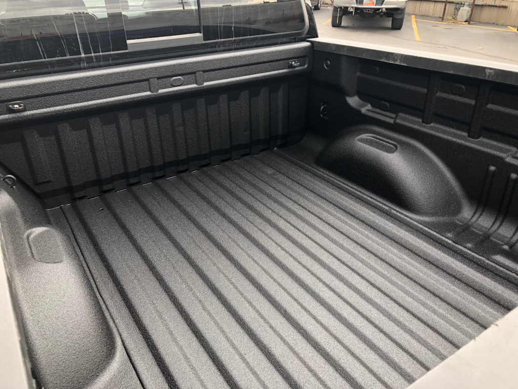
For the box I used some poppler wood with a cocoa stain, brass hinges, and magnets for the catch. The box overall was kind of an experiment because I have literally only made one other wood box in my life. Honestly this one turned out better than I expected. And my dad has been keeping it on the kitchen table because he says they are too nice to keep in the garage for now. This post is arriving a little later than planned... man why are the holidays so hectic? Early in November I decided that one of the first things to get done was a little bed protection for my regular daily driven car. That came in the form of a spray in bed liner from our local Rhino Linings shop. They did an amazing job and now the bed won’t look like a war zone after loading the usual suspects like dirt bikes, gravel, metal, and yard equipment... Once the lining in the bed was complete it was time to get a jump on making a christmas gift for my dad. I will wait to reveal the finished product until after christmas in the December post but this may give you an idea. this was an important step in my manual machining abilities. up until this point I had never done any single point threading for anything that was going to be used in something final. I decided to quite being a baby and see if I could do it on an actual part and not mess it up. I was happy with the end result but I did learn two things from my experience. One, this was probably a little too thin for the length of thread needed. it cut really well, but the middle of the threaded section was always a little tighter than the ends meaning the part was flexing in the middle even with the tail stock center supporting it. I had to chase the middle with the threading die to make it all uniform. It it probably best to single point thread longer lengths like this on thicker stock. The second lesson was that this takes forever I could have done this part in an eighth the time if I had used the threading die in the lathe. But if you don't have the right size die, this is a much cheaper alternative. Before thankgiving hit I was also able to start on another project for my 3 year old daughter. She has been obsessed with my nut and bolt supply in my garage and loves threading the nuts onto the bolts and pretending to fix things with them. I figured a good way to stop her from raiding my supply would be to build her a bolt together box that she could build and take apart at will with a single tool and the same bolts for every piece. on top of that she could also store a collection of nuts and bolts in it when done.
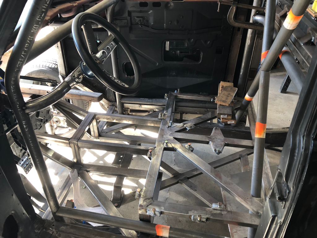
The first step was to create a design in fusion 360, which meant it would be a little more complicated of a design than it needed to be... but hey it will be cool. then onto the actual fabrication. My progress so far is documented in the timelapse video above. layout and rough cutting on the bandsaw went well other than a dull blade in the middle of it all. squaring up cutting to final size also went well, though next time i will probably do all the cutting on the mill to save time. the last bit of progress on the box was in the form of the top section that will have the sides bolted to it. this also went well, though I did not clear the chips as often as i should have and it resulted in a less than stellar finish. overall I think the time-lapse above covers about 8 or 9 hours worth of work over a couple of nights, though some of the more boring parts are not shown. more content to come in December, and even some drift stude updates. Okay I’ll admit it. I have been putting off working on the stude on purpose. The part of the stude that I wanted to do next, was related to the stuff that I have been working on lately, namely the steering linkage. Continuing on that theme would have meant that I do the headers next. But in order to do the headers the way they need to be done will require a significant purchase, one which I do not have the money for yet... so with a lack of funds the part of the truck that needed some progress was finding a better way to mount the cab to the frame. I started this project a few years back, but it just isn’t as fun as building a set of headers, so I put it off for a good long while. Once I got over the mental block, it was time to pull off the door bars, take out the seat, seat frames, and removed the bolts that had been holding the frame down. These bolts were kind of a pain to get out and are the real reason I am changing how the body mounts. First the bolts are not laid out in a way that makes them easy to get to, and second they basically sandwich two 2x1 square tubes together, and over time they will slowly collapse the tubing, as there is no solid structure around where the bolts go through. My goal is to make the bolts easy to access should I need to remove the body for any reason, and make it so a flat solid plate mounts to another flat solid plate so there is not chance of collapsing a tube.
Well... Here is it mid Sept and I have finished a project. Sadly it is not the Drift Stude, and you will have to settle for a finished wheelbarrow instead. Though this means, and I am promising here, that I will do some much needed drift Stude work now. I left you last in august doing some keyway broaching on the bushing inserts for the wheels and with the lathe apart for cleaning... The cleaning went well and I managed to free up the taper attachement, just in case I ever need it in the future. I left the old cross feed screw and nut in there, but plan to replacement in the near future when my wallet will allow. With everything cleaned and oiled it was time to get moving on some wheelbarrow parts. first up was the hub for the sprocket. This like the hubs/bushings for the wheels needed to have a keyway cut, but also was a bit more complicated because it needed to have a bolt circle drilled and tapped and as well. It turned out really well and the only problem I really had was cutting the aluminum slug down to size after the first machining process. The bandsaw for some reason didn't really like this big of a piece of aluminum... One other slight problem I had was with the bolt circle. The DRO that came on my mill has a bolt circle function, but I found out when I went to go use it on this that some fo the buttons on my DRO do not work. Namely the equal button, which is needed for the bolt circle function and also some of the other functions. I will have to address the DRO issue later, but for not it worked to pull dimensions off of a CAD drawing I did for the part and use the functional scales part fo the DRO to dial it all in manually. The end result was the same and worked great. I also managed to get some cool time lapse footage of the lathe machining below At the end of July I teased that I was going to work on my skills as a machinist by doing a few tool projects. Early in August it was time to finish the tool makers clamp. In keeping with that promise I kept up on making the tool makers clamp. The Next step: threading the knurled screws. I opted to use a die rather than single point thread as I didn't want to screw up the pieces I had made thus far because I'm not great at single point threading. I kicked the lather into its lowest back gear setting and chucked the rod in the tail stock drill chuck. And let the die/chuck drag the screw inward as it cut the threads. It worked like a charm. Next up I drilled cross holes for increased leverage when tightening... though I doubt ill need them. Turning down the threaded end of one and Parting off to length came next.
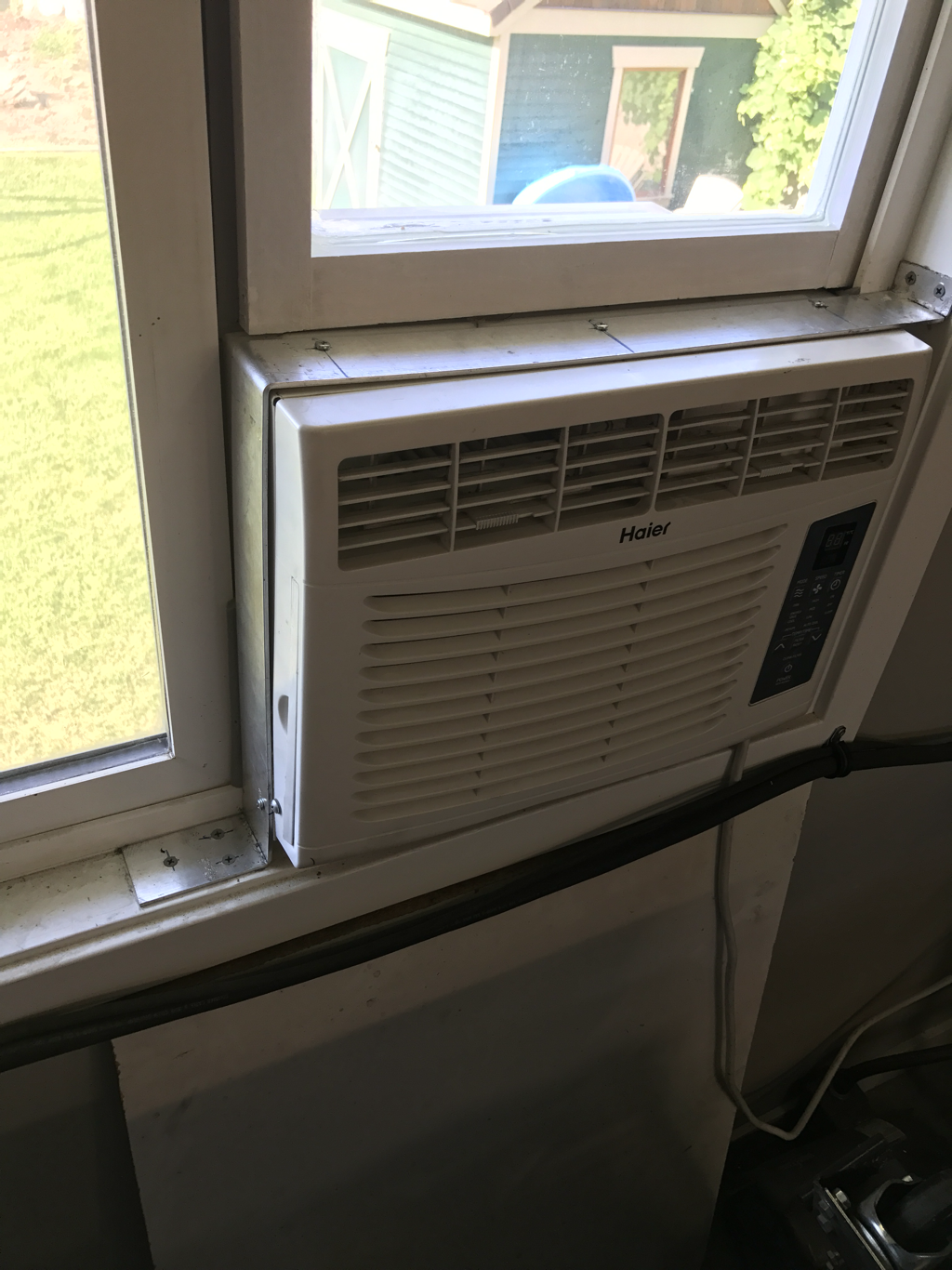
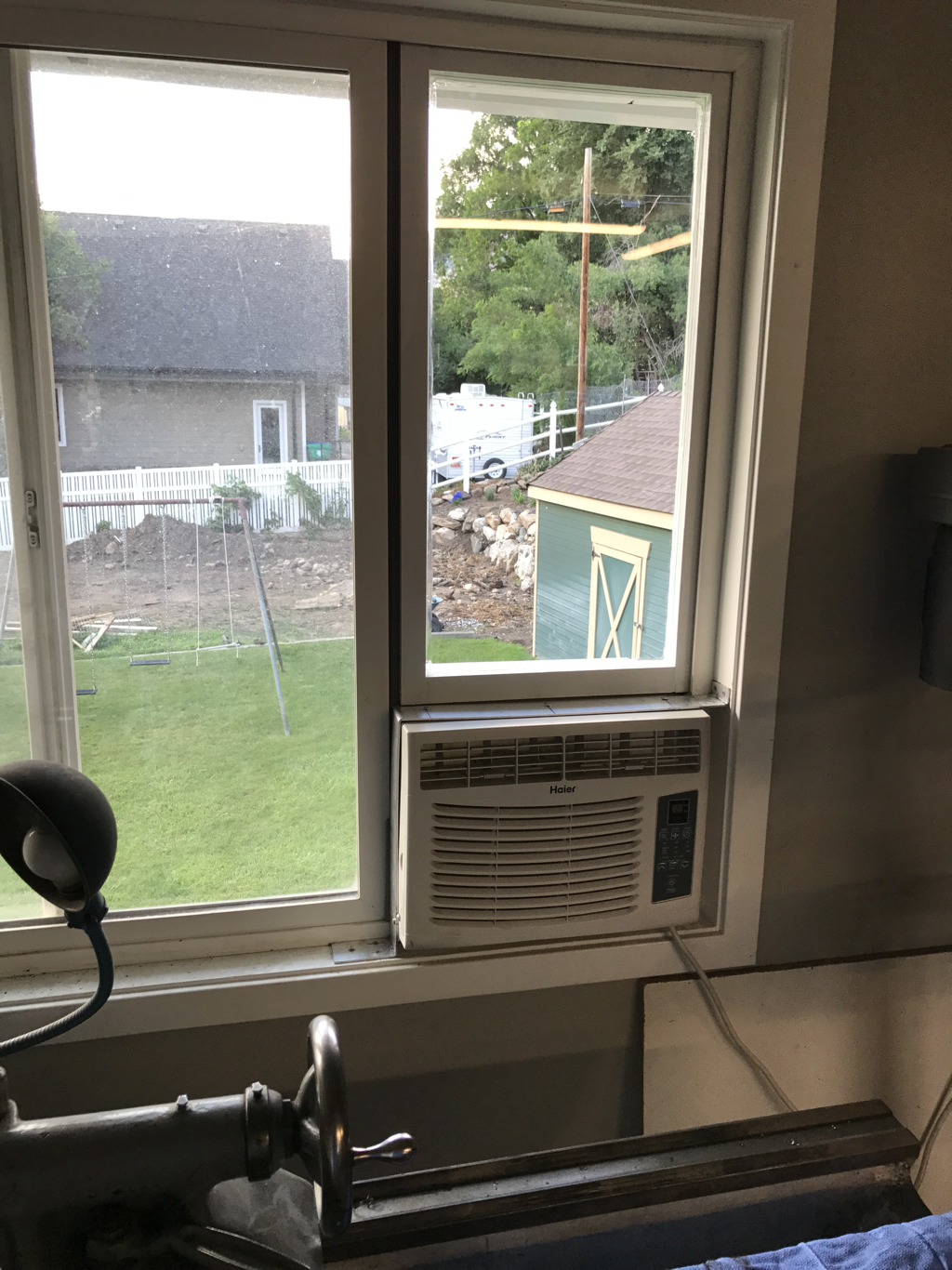
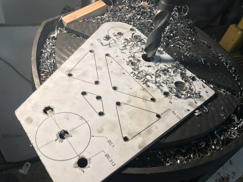
First things first, it was getting pretty hot here in Utah come the end of June so I had resolved to put in a little air flow to the garage via a windo air conditioner unit. I was able to get this one for nothin, as it was my sisters old unit she had had in an old apartment. I whipped up a quick aluminum strap from scrap and screwed it down. Next up I had to spend a bit of money and build a window frame. My wood working skills are far from good, so I opted to build a frame for a single pane of glass, my mortise and tenon joints sucked, so i opted to just to flat cuts and glue 3 sides and screw in the 4th so I could set the glass in a recess before final assembly with some clear cault to seal the glass. Overall it didn't turn out half bad, and some weather stripping helped seal all the gaps. now that the shop had a little air flow in the 100 degree temps it was time to get working on the relocated steering colum. I had started redesigning the mount for the colum and pedal assembly in Fusion 360 in the last post as seen here. Rather than calling up my buddy to plasma cut a single part, i opted to do this one the semi old fashioned way by printing out a 1:1 scale paper template and transferring all of the elements to a plate of steel. This was accomplished by gluing the paper to the metal, cutting the outside shape on the band saw, center punching each radius, then drilling the appropriate holes. The big circles were drilled to .75" to fit by knockout punch set. The lightening triangles in the middle get the radius corners drilled and then the ill finish the cutting with a die grinder. Overall this makes for a pretty accurate bracket...
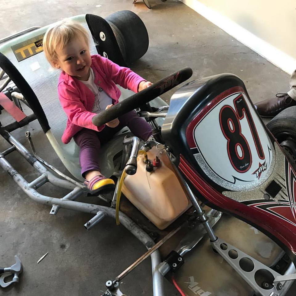
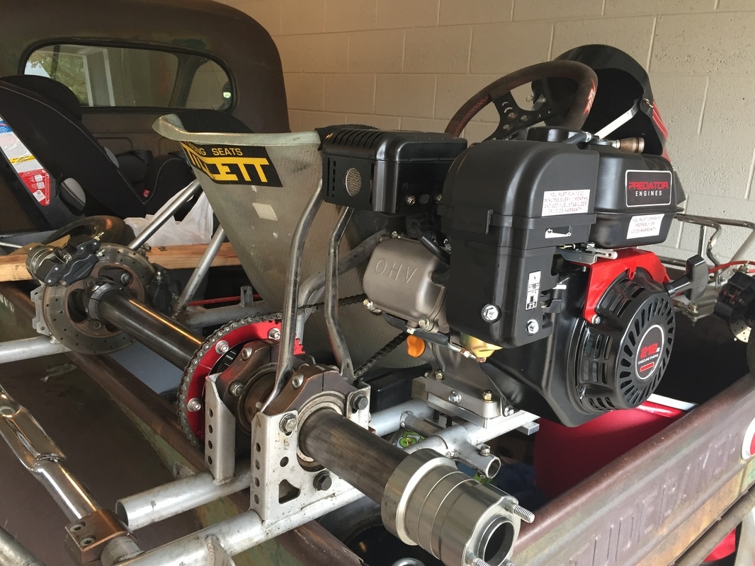
Well, 9 months has passed since my last post... you'd think the drift truck would be done by now wouldn't you? Nope, not even close but thats the nature of a project where new things are being learned as you go, and you factor in family, friends, trips, home, money and other distractions. Things can take a while. Speaking of distractions...some time after my last update I decided I needed a go kart and I had big plans of making it a remote controllable cart so I could give my toddler daughter rides, where she thought she was driving, but in reality I was in control. at the same time i thought it would be cool to buy a cart that would work for dad(me) as well. I ended up finding a sweet deal on an older shifter kart which was a PTK 125cc shifter kart chassis. it also came with a Honda CR 125 motor that was in pieces and needed to be rebuilt. This kart is really a competition shifter kart that had a bunch of magnesium hub parts and had front and rear hydraulic brakes, shift linkage, clutch controls, etc... basically the go-kart I always lusted after. Here is the kart a few days after the purchase. I got the kart and motor for $400. In reality I knew that throwing a 125cc two stroke in there to begin with would be terrifying for my daughter if I stuck to the original RC kart plan... so I opted to shelve the motor for a few years and go after a 4 stroke harbor freight motor for it. I, like many before me, chose the Predator 212cc motor and on during a harbor freight sale i picked up a brand new one for $99. After another $150 in other parts including a clutch set, motor mounts, sprockets, sprocket hub, and chain, I had the motor mounted some small issues fixed and the kart ready to drive.
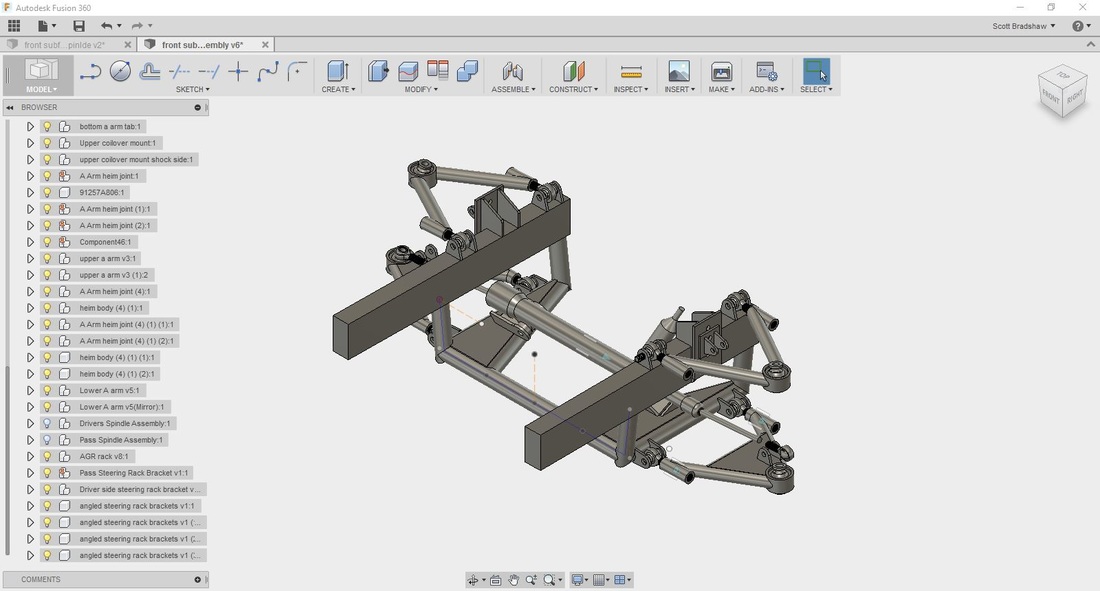
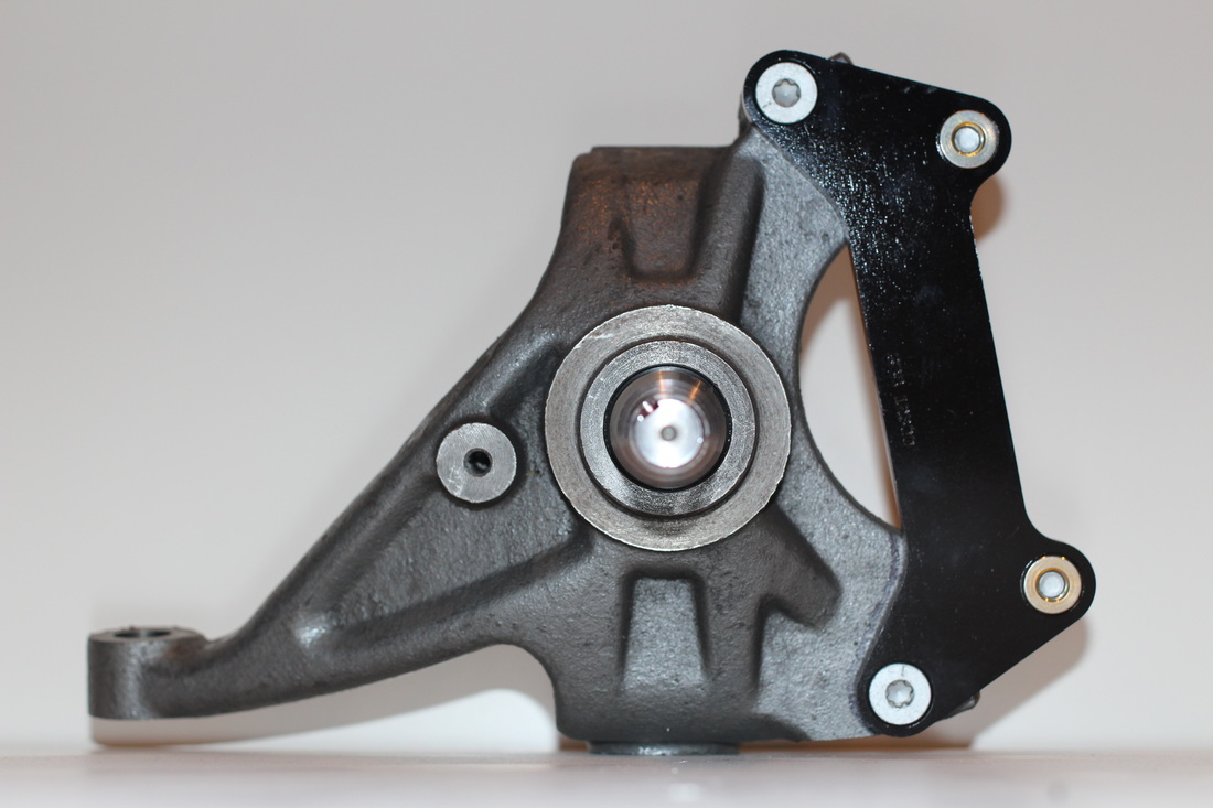
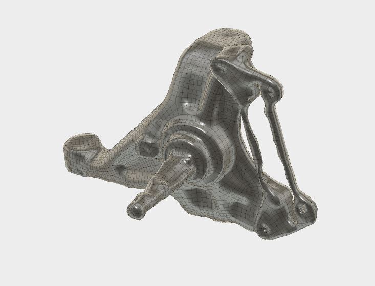
Now that the rear brake/axle setup is done it was time to move onto the front suspension again. Now, if this is the fist post you ever read of my build blog let me fill you in on a couple of deets. First, I am learning as I go. This is my first build involving major suspension design and fabrication. Second, I have had the front suspension and steering all set up once before, but upon closer inspection I was not getting the correct steering angles, and my ackerman geometry was all sorts of wrong. Third, I am trying to maximize steering angle for better handling while drifting. As mentioned in the last post the first thing to do was to finish drawing the front suspension in Fusion 360. I did this by taking measurements from the real thing, since they were never drawn in a real cad program to begin with, and slowly piecing it together. I drew a really rough AGR steering rack as well since it would be needed for the steering geometry measurements. The reason I was going through all this trouble was to save my self fabrication time and most importantly money, since the redo's were getting a little out of hand. as you can tell from the picture above I had one last component to draw, the spindles. these were proving to be a bit above my cad skills so I had to get a little creative. At first I tried taking precise measurements off of the actual spindle and drawing in Fusion. but that was just not working given the many different curves and angles of the damn thing. Next I decided that I was going to see if someone could produce a laser scan of the spindle so I could turn it into a solid cad model... that proved to be to expensive. The nearest company I could easily find was in Washington and wanted $500 for the work. which is the price of another 2 sets of spindles, so that meant I could screw up 2 other sets, besides the one I had before that would be a viable option. So after a few weeks of wondering what to do I decided to try Pictometry Scanning. This is a fairly new process that involves taking lots of pictures of something at all angles and then letting a program combine them all into a 3D mesh model. I had to do it a few times in order to get the pictures done in a way that would produce a recognizable part, but in the end I had usable 3D mesh data that I could use to turn into a solid model and use in my steering design calculations. One thing I learned is that creating a 3D model this way does not work well when the surface is shiny. you can see I had problems with the gloss black powder coated Wilwood brake bracket and the spindle part of the knuckle.
|
Download the
following Designs used in this build: Archives
February 2018
|
