|
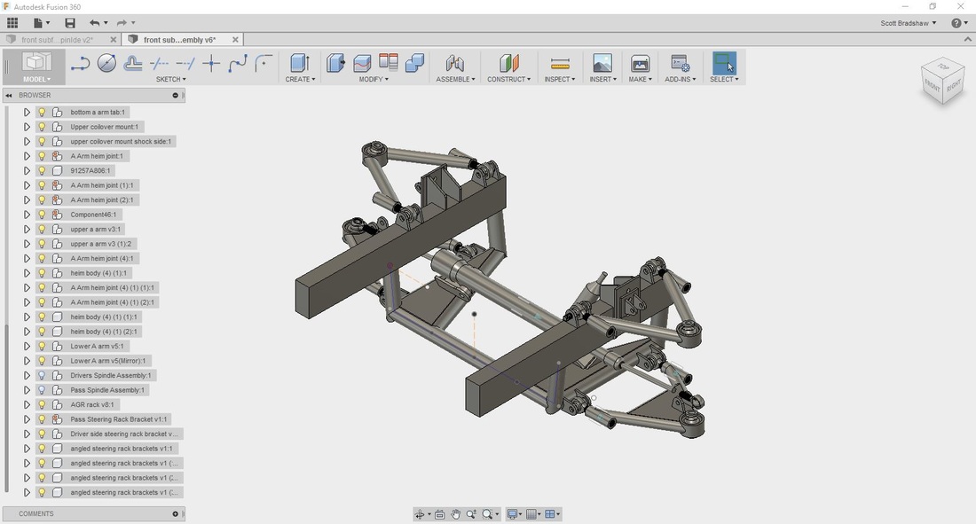
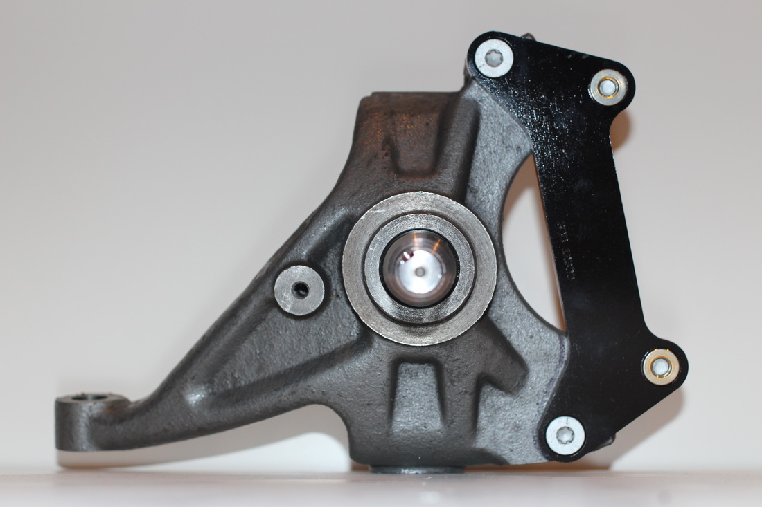
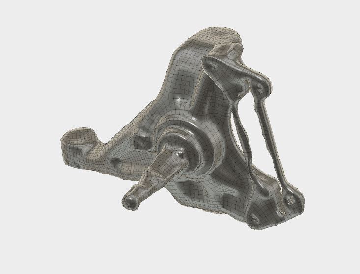
Now that the rear brake/axle setup is done it was time to move onto the front suspension again. Now, if this is the fist post you ever read of my build blog let me fill you in on a couple of deets. First, I am learning as I go. This is my first build involving major suspension design and fabrication. Second, I have had the front suspension and steering all set up once before, but upon closer inspection I was not getting the correct steering angles, and my ackerman geometry was all sorts of wrong. Third, I am trying to maximize steering angle for better handling while drifting. As mentioned in the last post the first thing to do was to finish drawing the front suspension in Fusion 360. I did this by taking measurements from the real thing, since they were never drawn in a real cad program to begin with, and slowly piecing it together. I drew a really rough AGR steering rack as well since it would be needed for the steering geometry measurements. The reason I was going through all this trouble was to save my self fabrication time and most importantly money, since the redo's were getting a little out of hand. as you can tell from the picture above I had one last component to draw, the spindles. these were proving to be a bit above my cad skills so I had to get a little creative. At first I tried taking precise measurements off of the actual spindle and drawing in Fusion. but that was just not working given the many different curves and angles of the damn thing. Next I decided that I was going to see if someone could produce a laser scan of the spindle so I could turn it into a solid cad model... that proved to be to expensive. The nearest company I could easily find was in Washington and wanted $500 for the work. which is the price of another 2 sets of spindles, so that meant I could screw up 2 other sets, besides the one I had before that would be a viable option. So after a few weeks of wondering what to do I decided to try Pictometry Scanning. This is a fairly new process that involves taking lots of pictures of something at all angles and then letting a program combine them all into a 3D mesh model. I had to do it a few times in order to get the pictures done in a way that would produce a recognizable part, but in the end I had usable 3D mesh data that I could use to turn into a solid model and use in my steering design calculations. One thing I learned is that creating a 3D model this way does not work well when the surface is shiny. you can see I had problems with the gloss black powder coated Wilwood brake bracket and the spindle part of the knuckle.
5 Comments
|
Download the
following Designs used in this build: Archives
February 2018
|


