|
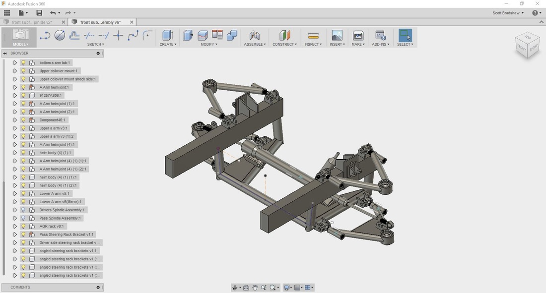
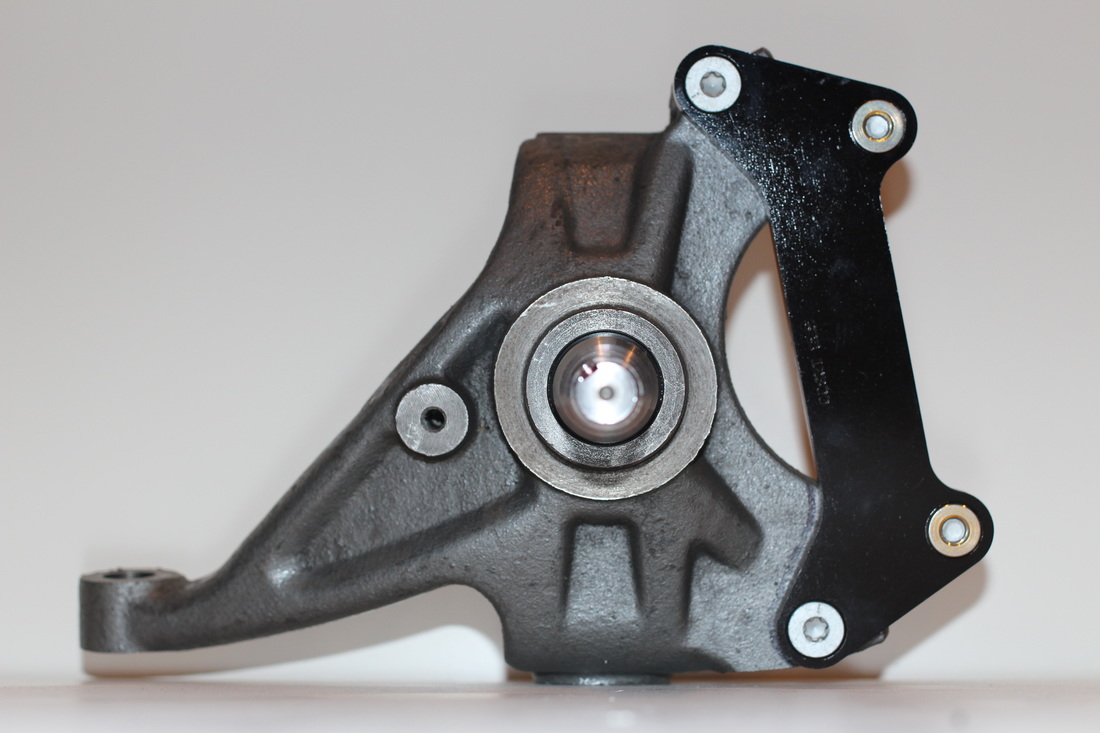
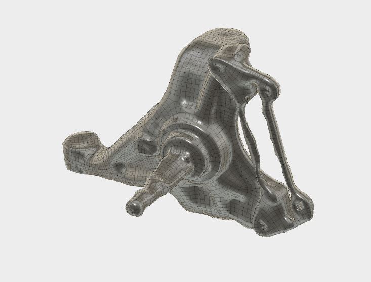
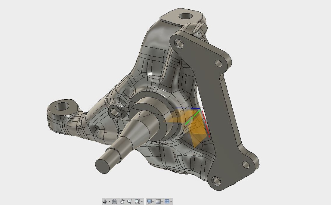
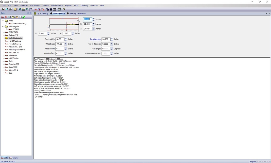
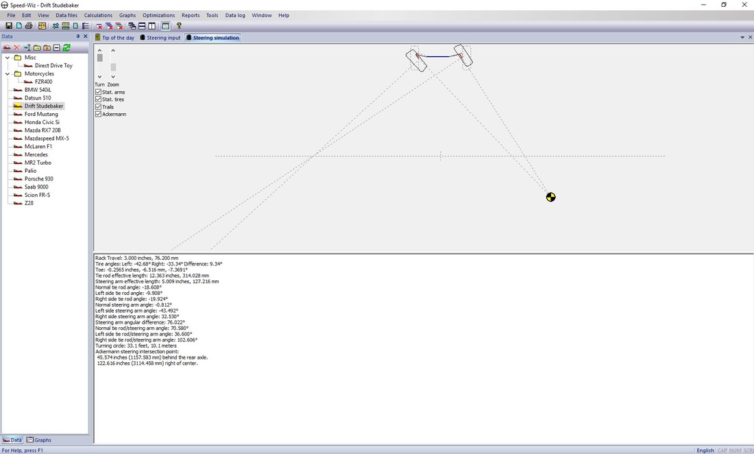
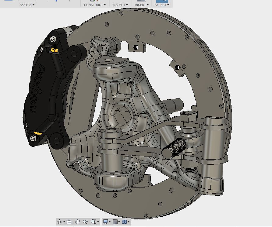
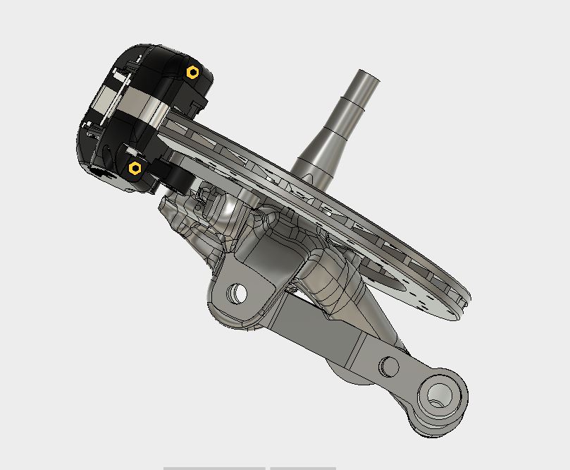
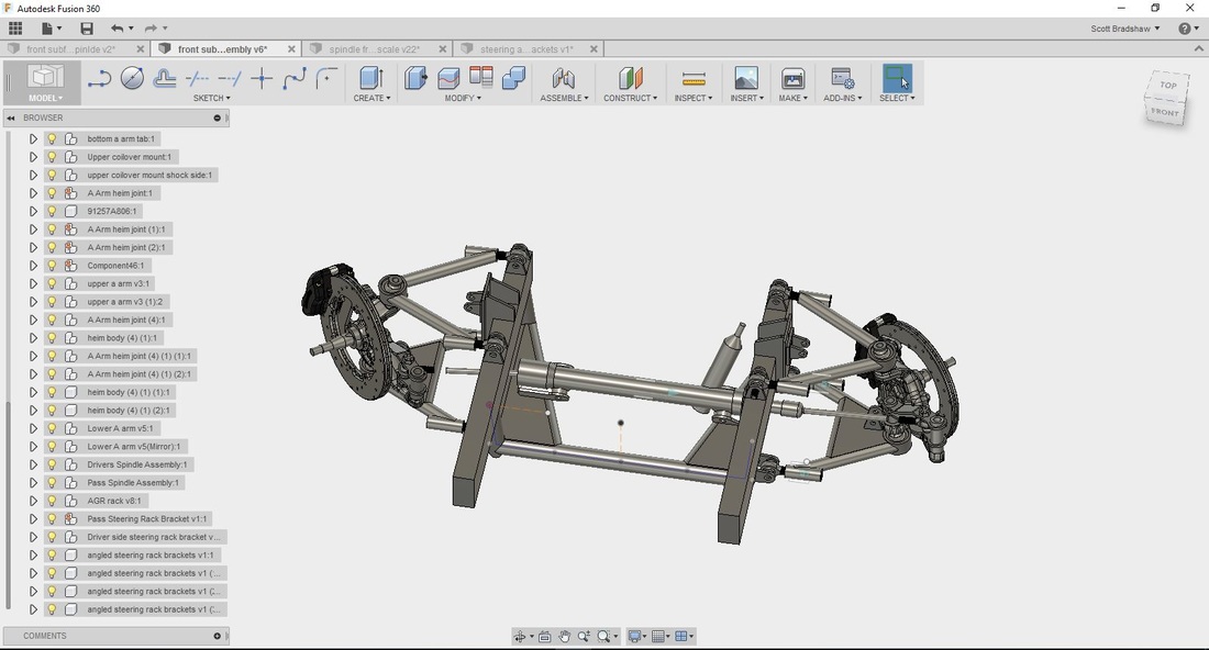
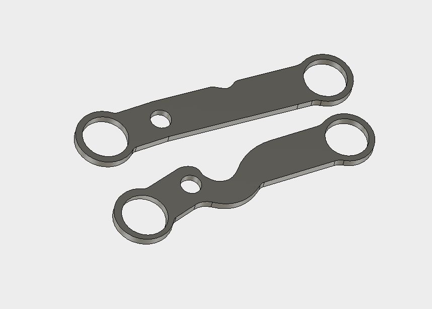
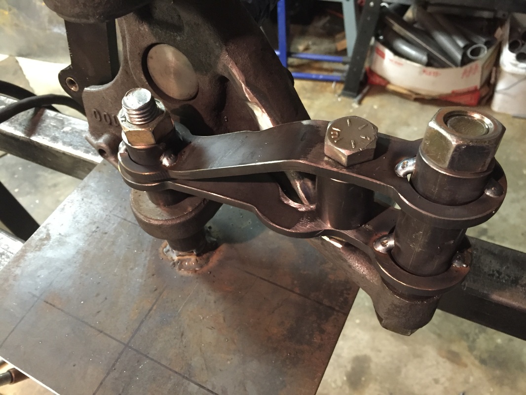
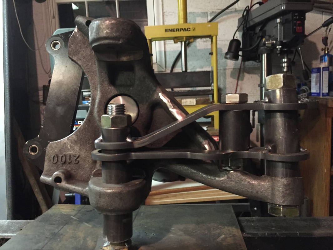
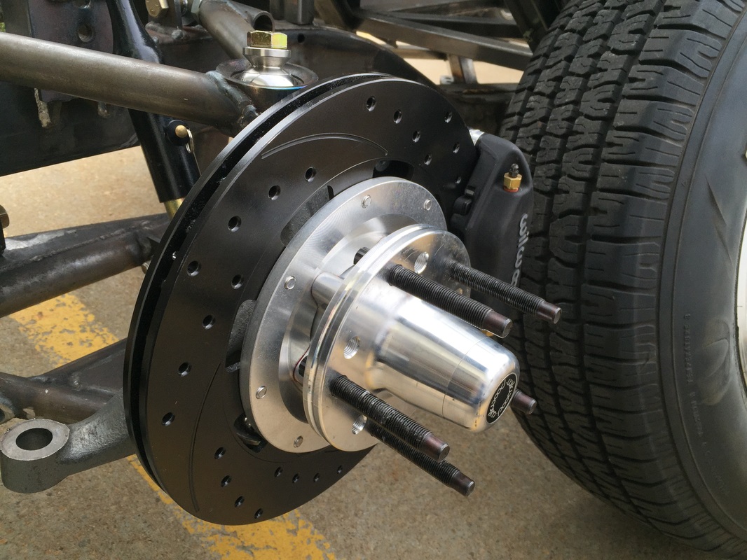
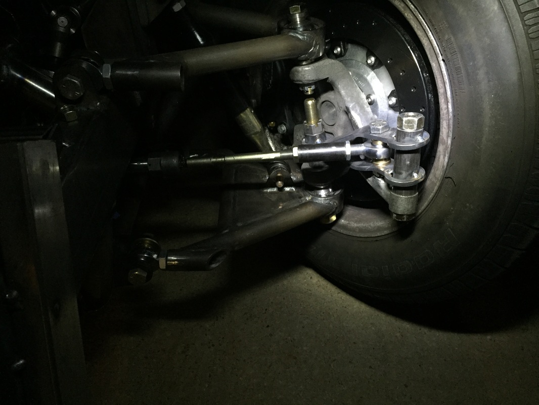
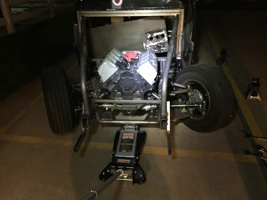
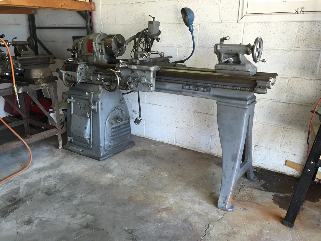
Now that the rear brake/axle setup is done it was time to move onto the front suspension again. Now, if this is the fist post you ever read of my build blog let me fill you in on a couple of deets. First, I am learning as I go. This is my first build involving major suspension design and fabrication. Second, I have had the front suspension and steering all set up once before, but upon closer inspection I was not getting the correct steering angles, and my ackerman geometry was all sorts of wrong. Third, I am trying to maximize steering angle for better handling while drifting. As mentioned in the last post the first thing to do was to finish drawing the front suspension in Fusion 360. I did this by taking measurements from the real thing, since they were never drawn in a real cad program to begin with, and slowly piecing it together. I drew a really rough AGR steering rack as well since it would be needed for the steering geometry measurements. The reason I was going through all this trouble was to save my self fabrication time and most importantly money, since the redo's were getting a little out of hand. as you can tell from the picture above I had one last component to draw, the spindles. these were proving to be a bit above my cad skills so I had to get a little creative. At first I tried taking precise measurements off of the actual spindle and drawing in Fusion. but that was just not working given the many different curves and angles of the damn thing. Next I decided that I was going to see if someone could produce a laser scan of the spindle so I could turn it into a solid cad model... that proved to be to expensive. The nearest company I could easily find was in Washington and wanted $500 for the work. which is the price of another 2 sets of spindles, so that meant I could screw up 2 other sets, besides the one I had before that would be a viable option. So after a few weeks of wondering what to do I decided to try Pictometry Scanning. This is a fairly new process that involves taking lots of pictures of something at all angles and then letting a program combine them all into a 3D mesh model. I had to do it a few times in order to get the pictures done in a way that would produce a recognizable part, but in the end I had usable 3D mesh data that I could use to turn into a solid model and use in my steering design calculations. One thing I learned is that creating a 3D model this way does not work well when the surface is shiny. you can see I had problems with the gloss black powder coated Wilwood brake bracket and the spindle part of the knuckle. I was able to re draw those parts and scale it to size. I was confident that his was within about an 1/16th of an inch true to size and shape of the real thing. I also cut the appropriate holes in the model since those did not translate well either. Now that the Spindle was officially a model it was tie to think about how to get the most angle while keeping the ackerman angles close to correct. For this I discovered a nifty little program called Speedwiz. I can't remember exactly but I think I was googling steering geometry terms like ackerman, and rack and pinion etc... and came across this program which would let you input measurements and give you some written and graphic simulations. it was $25 or $30 and well worth it in my mind. I started by plugging in my known measurements from my 3D design and then played with the variable things I hadn't finished yet such as the front to back placement of the rack and pinion, and the length and angle of the steering arm part of the knuckle. I found the best of both worlds, steering angle and ackerman at the measurements in the above picture. and this was the simulation it produced with 3" of rack travel. you can see that the imaginary center lines of the wheels intersect at the wheel base which is what I want for ackerman geometry, and you'll have to take my word that this also is the best steering angle I could achieve while maintaining those ackerman angles. Up next was to design a bracket that could bolt onto the s10 spindle that would give me this geometry for the steering arm, while at the same time staying out of the way of the spindle itself and all fo the other brake components, and suspension components on the car. after many hours thinking and designing and re-designing this is what i cam up with. If you look closely you can see I did have to take a chunk out of the actual cast arm on the spindle to make room for the nut and bolt for the steering heim joint, but it still leaves plenty of material to give the arm enough strength to support the new bracket. This design also will give me the chance to use my Swag Offroad press brake. with this view you can see that new steering arm bracket has a slight angle to the outside of the car and has cutouts to work around the existing cast spindle parts. now the front suspension and steering is totally 3D cad modeled and everything checks out. Time to start making real parts and get the steering checked off the list. from there I had to do some guess work in order to flatten out the design so it could be cut and then bent after. I did some research on K-Factors and got no where so I decided to bend some test pieced with my press brake, measure the use of material through a 90 degree bend and add a percentage of that much material back into the flattened design based off the angle I was going to be bending them. In all honesty it worked, but I was a bit off in my calculations and the only way it worked was to oversize the holes for the spacers that bolt to the spindle. but hey those are going to be welded up anyways. so a less than perfect fit up on them is okay, plus it allowed me to place the brackets at an angle since the flat parts of the steering arm are at a different angle than the a arm mounting points... Now off to my buddy Nicks shop to have the brackets cut out on the CNC Plasma table. Parts got cut, and bent, and everything turned out pretty darn good. as you can see the press brake did wonders(pictured in the background) and I was a little short on how much material to compensate for during the bending but the mount holes made up for the miscalculation. I am very pleased with these results. while all the brake components were off I decided to put my 3" long wheel studs on. they look pretty racy... by the time I got every thing tacked and bolted back together it was pretty dark, but still had to show off the new hardware and steering angles. A little wider shot to show the angles better. all that is left is to final weld the new brackets and the steering rack brackets and then I can start on the steering wheel linkage. Last but not least I added a new tool to the garage. This is a 13" Southbend Lathe. this thing is a monster compared to the other 9" lathe on loan from my friend Nick. It will need a VFD drive in order to run and some bigger tooling, but it'll take the place of the ole' 9" inch which is going back to Nicks shop now that I bought my own.
And with that you are up to date on the Drift Studebaker as of 09/07/2016. Progress may be slow, but its getting closer. stay tuned.
5 Comments
Stephen
3/18/2017 05:12:01 pm
Hey, any chance you'd be willing to share the Fusion model for the s10 knuckle, I'm using those in my project too.
Reply
3/21/2017 02:33:20 pm
Hey Stephen,
Reply
Bradley
2/20/2018 12:15:37 pm
Hey man I was curious if you were willing to shoot me the schematics for these? I'm working on a s10 drift project and would love to try and Fab these up.
Reply
Zachary C.
3/9/2022 11:12:33 am
Hey Scott,
Reply
Leave a Reply. |
Download the
following Designs used in this build: Archives
February 2018
|
