|
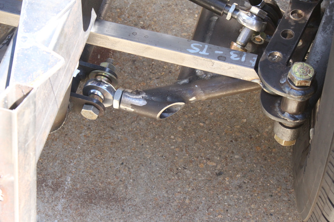
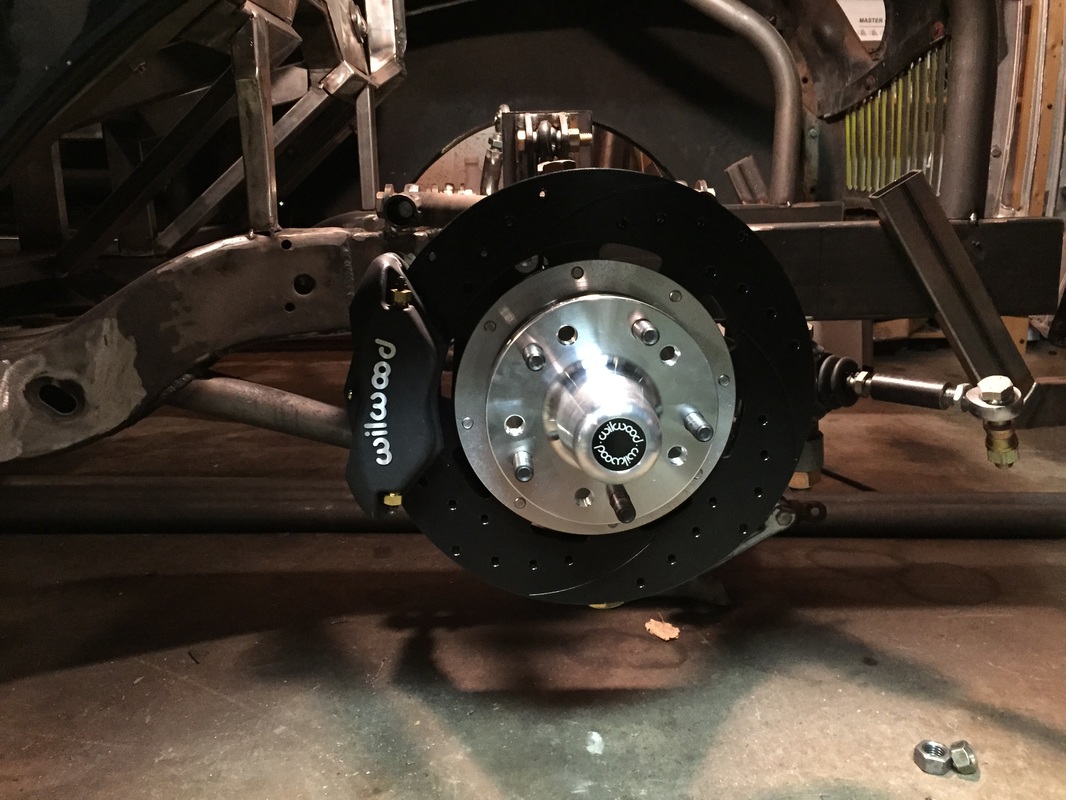
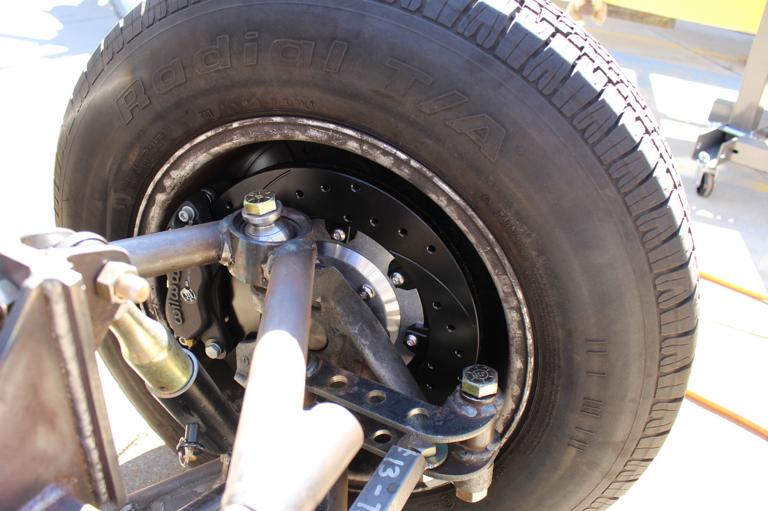
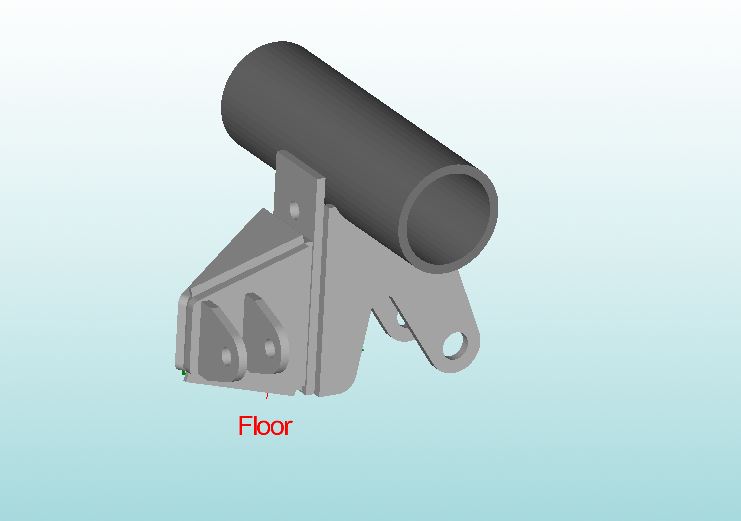
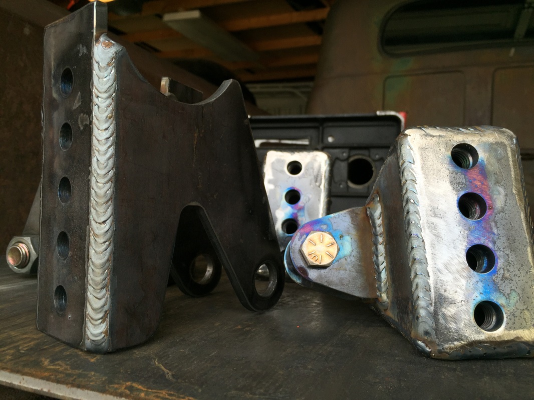
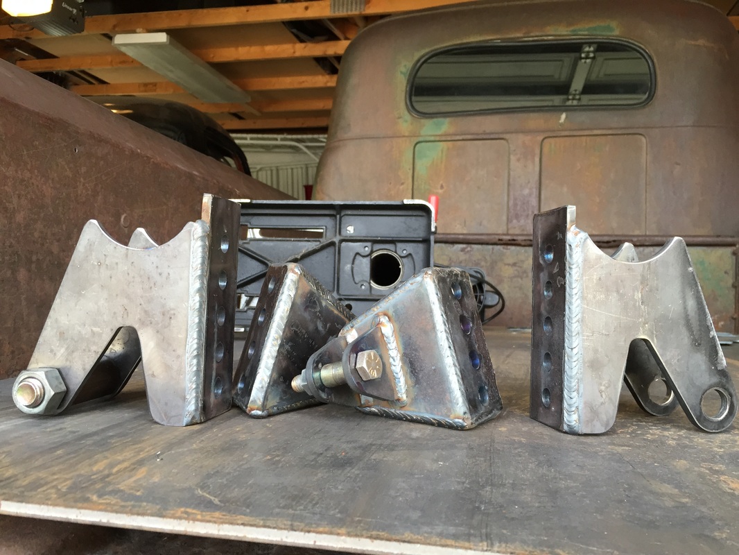
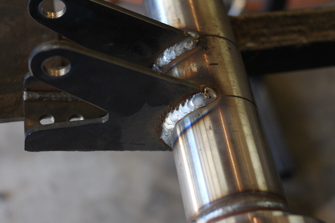
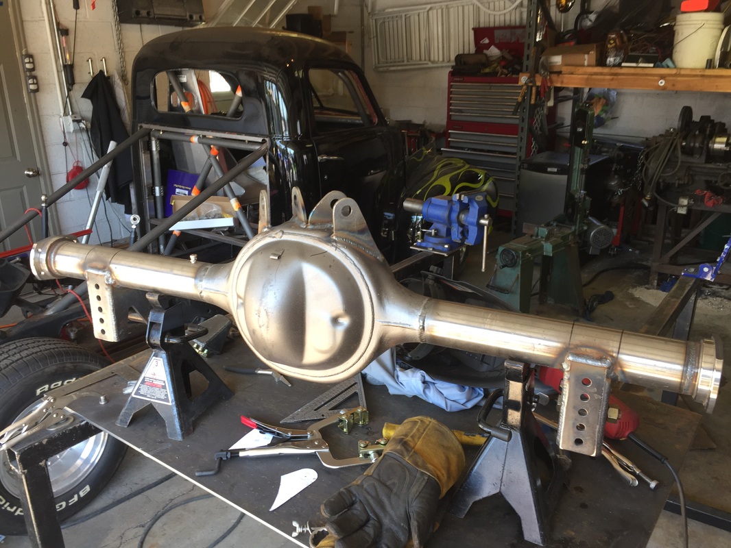
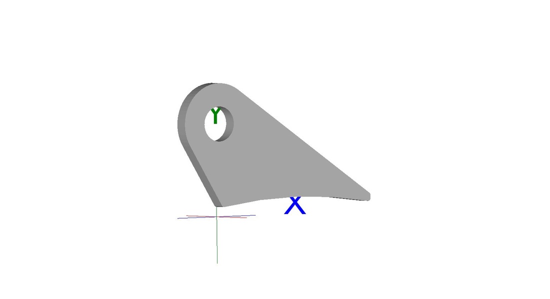
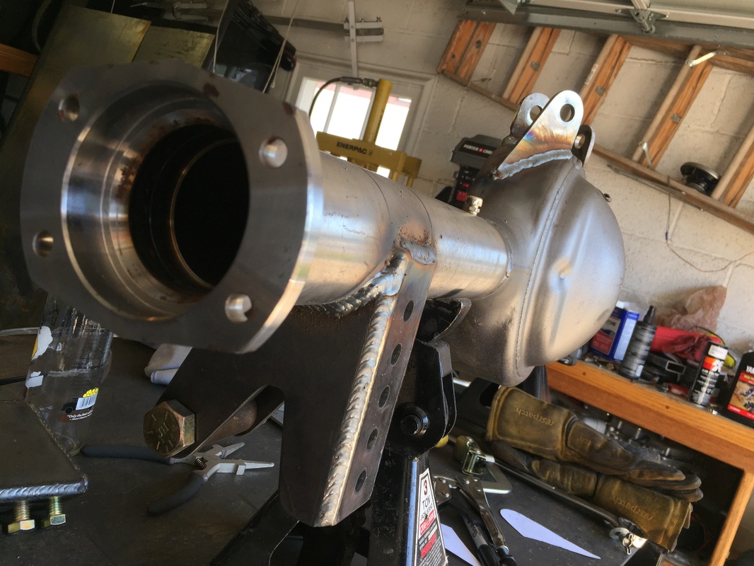
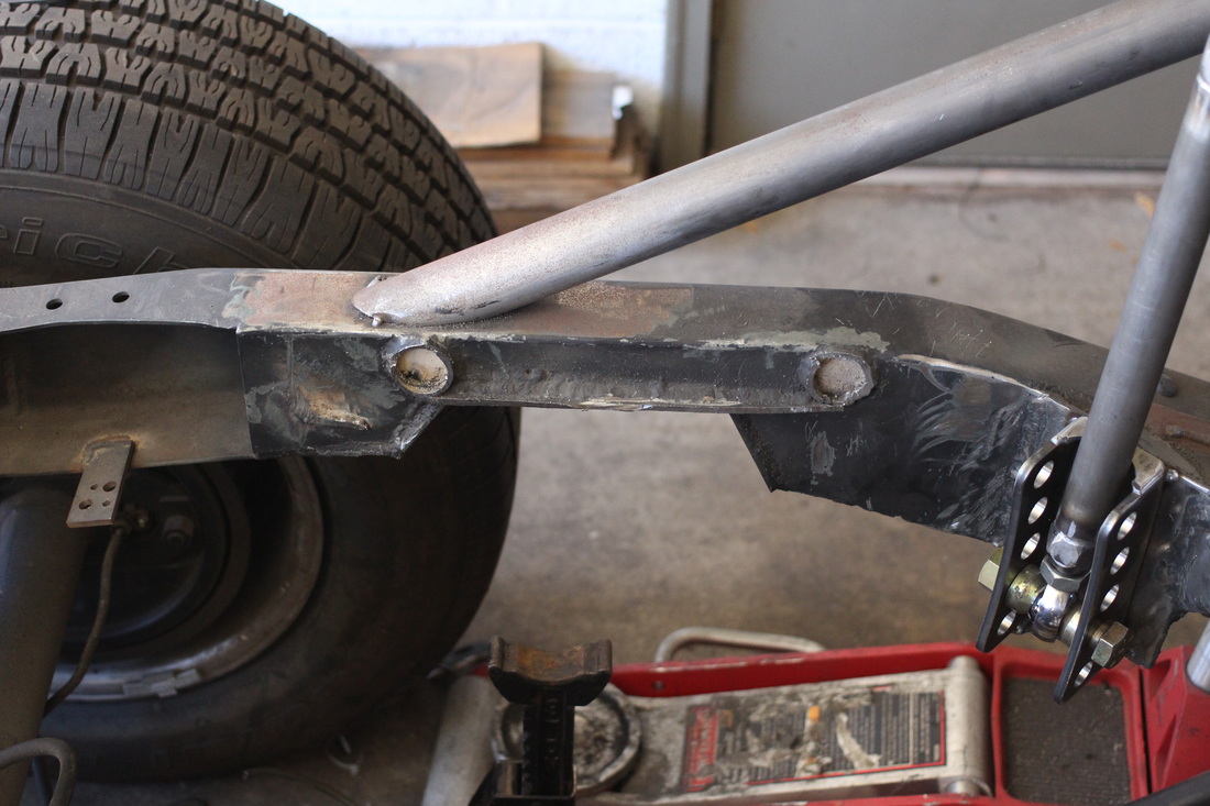
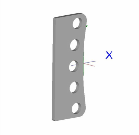
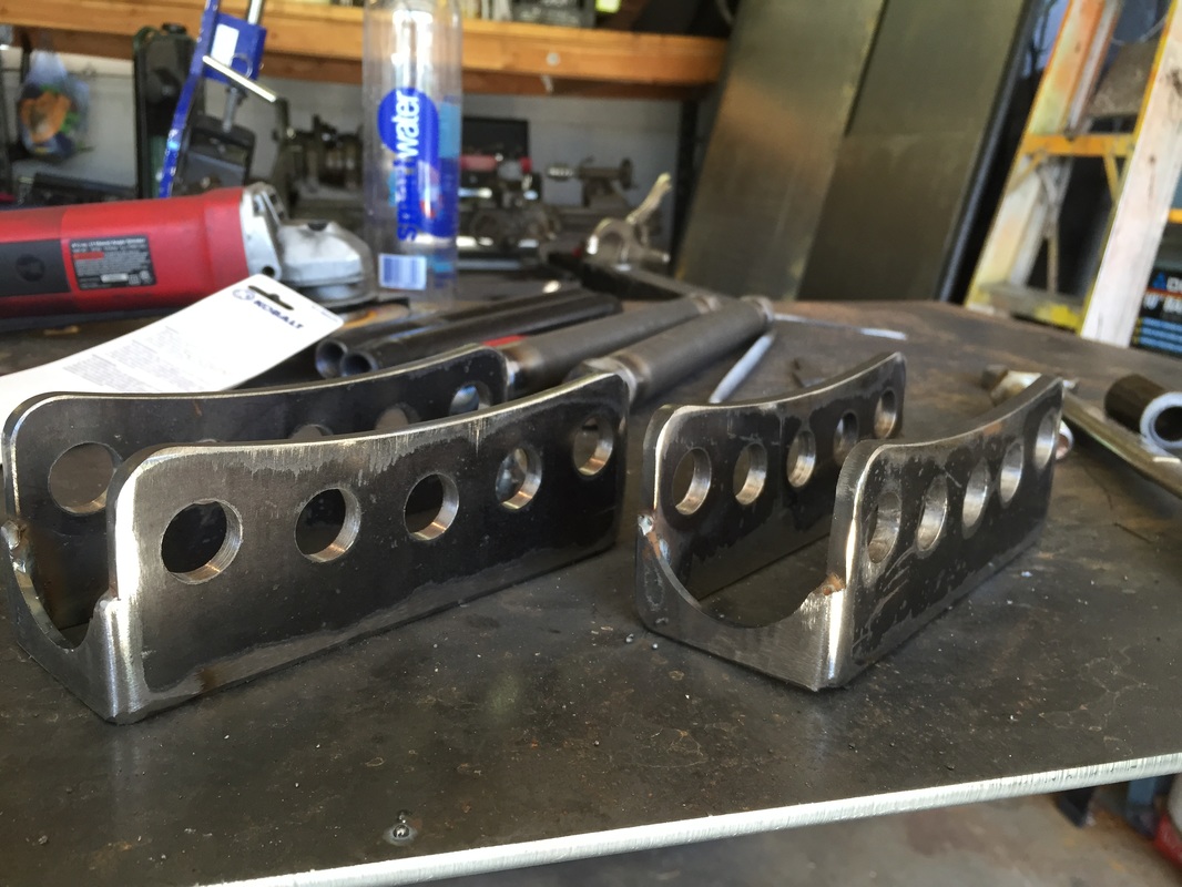
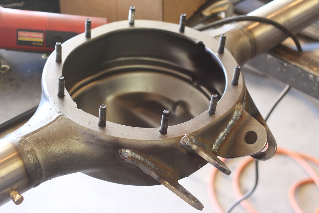
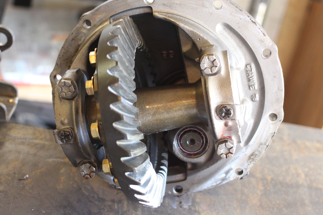
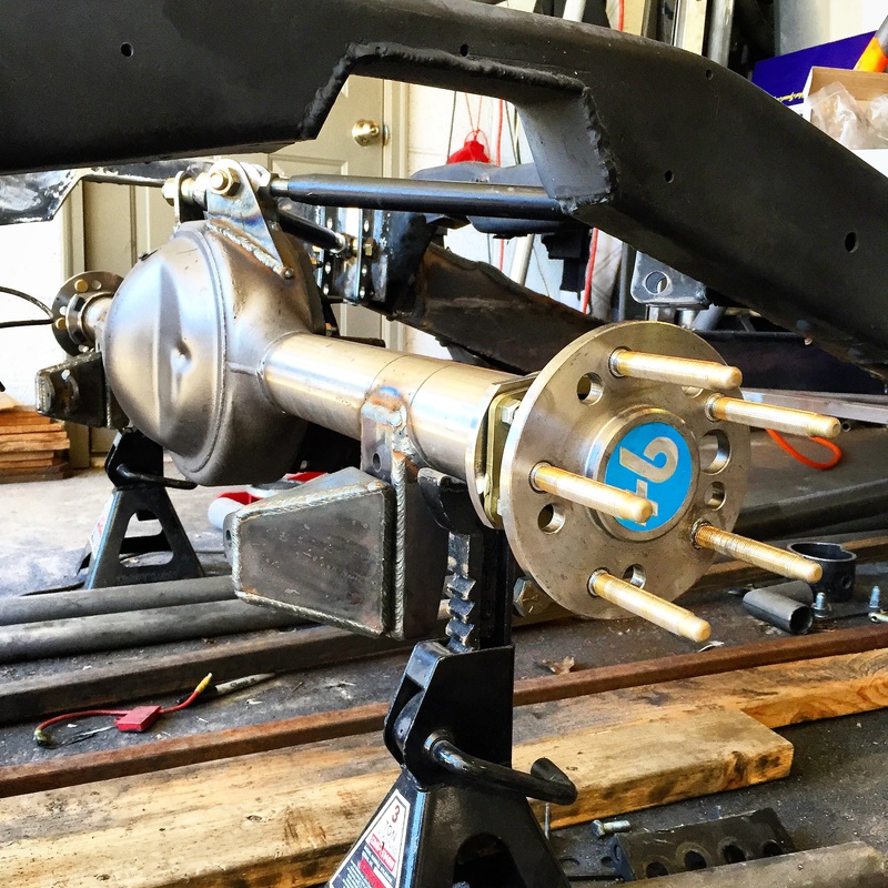
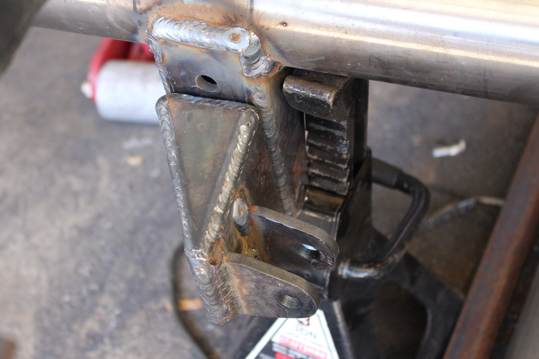
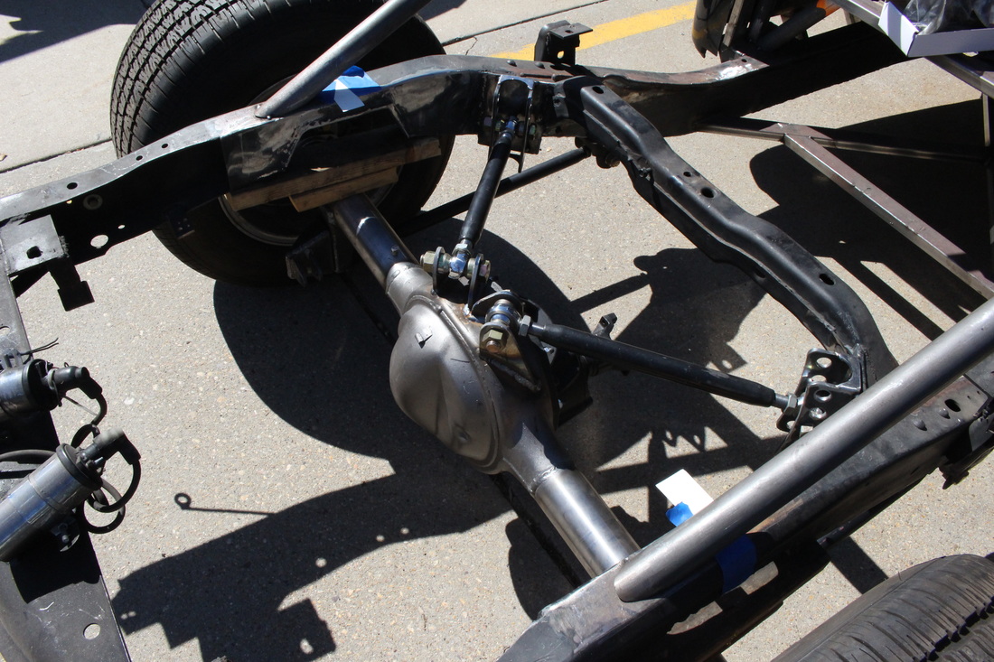
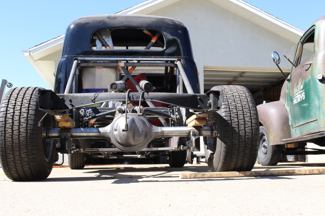
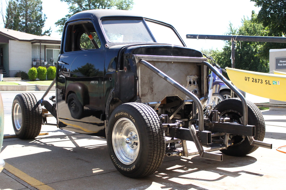
It has been almost a full year since my last build post, and for that I apologize. Since December 2014 my life has been a bit of a whirlwind. My wife gave birth to our first child mid December and since then my time in the garage has been limited. But little by little I can sneak away and get in there. I have even found time to re-vamp this website a bit. You will notice that I have removed all the content that wasn't associated with the builds in my garage and I have added a library of designs used in the this build and others. The reason behind adding my designs is so people can use them in their own designs or create their own stuff using my designs to help generate their own ideas. I would have loved to have something like this from the beginning of this project, so hopefully it helps someone... Now onto what I have completed over the last 9 months: And the first bit of progress isn't actually progress. Nope its a few steps back. After the last post where I had the steering all hooked up I noticed some problems. The biggest one was that the ackerman geometry was off which was causing the outside wheel to be turned in at more of an angle than the inside wheel at full lock. This is the opposite of what it should be. you can see if the picture above that there is tubing in place of the rack and pinion. this is so I can roll it out of the garage without having to battle the front wheels individually as it rolls. What you don't see, and what I failed to get a picture of, is that the rack and pinion mounts have been cut out. I will work up a plan to relocate it, but for now will focus on the rear suspension because that plan will have to involve different rack mounts, different engine mounts, and possible notching the frame rails in order to clear the rack. More on all of that in a later post. Now onto some actual progress. I got the Wilwood Brake setup installed. this particular one is made to fit S-10 Spindles, and will fit 2" drop S-10 spindles like I have also. I am very happy with the results so far. Only a little modification was needed to the original spindle, in the form of trimming the original ears that hold the stock brake parts, and drilling and tapping some holes for the caliper bracket. All the details are included in the excellent instructions. I plan on using the same caliper for the rear, but will most likely use two on each side with one pair dedicated to a hydraulic e-brake. This setup tucks nicely into my 15" diameter wheel for now, but even though these clear I do plan on running some 17" or 18" wheels by the time the Drift Stude is road worthy. Another new feature I will be adding to this website is a list of all the parts, and tools, and pricing on each that have gone into this build. These brakes will be a good example of what will be listed in that list. Next on the list was to think about rear suspension link and coil-over brackets. After some thought I decided it would be a good idea to have some ride height adjust-ability but at the same time keep every thing strong using double sheer brackets for mounting. At first I tried to find something that would work from off the shelf parts, but like everything else on the truck there was nothing. so back to my trusty Bend Tech software to design what I needed. It took some time to figure it all out but I am extremely happy with the end result. This assembly is one of the downloadable files I have available in the design library. This is the final product based off the design. Since Bend Tech is limited to Plate and tube designs. I did not have captive nuts in the actual design, but had always planned to, and did use them in the actual bracket. I have also started machining spacers to use in between brackets so after tacking and final welding they are the perfect width to snugly fit whatever they are meant to hold. I wish i would have been doing this from the beginning as it would have saved me from re-doing some of the front suspension brackets, but hey I am learning as I go. for reference, the bearing ends on the Qa-1 coilovers are 1" thick. So in order to have the bracket fit well and not be too narrow come final assembly time I used a spacer machined to a total length of 1.020" and left it in while welding until fully cooled. works like a charm. I should mention that before I Designed these brackets I already knew the specs on the axle housing I was going to use, and I ordered it from Speedway Motors about the same time as I did the designs. The axle housing has a reclaimed Ford 9 center section with new axle tubes and flanges. for a total wheel mounting surface to wheel mounting surface width of 56". It also has the new ford Big Style flanges which will accept a ton of aftermarket disc brakes. The hosing came with 31 spline Currie axles and all the bearings and seals. The third member has to be ordered separately and I went with a Safety Team full spool third member with a 3.73 gear ratio. After many measurements I felt good about tacking the new brackets to the new axle, and then after some test fitting decided they could be welded on. The brackets were positioned in their final spot so that the pinion angle would be exactly 90 degrees perpendicular to vertical coil-over bracket mounting surface. this should give me some wiggle room in getting the correct pinion angle without running out of room in the bearing mount of the coil-over. The brackets for the upper triangulated links came next. The top links intersect the axle at just about a 42 degree angle, which means that the brackets on the center section of the housing need to be angled and contoured in order to match. the inner bracket were off the shelf and I cut off about 2.5" so they wouldn't interfere with each other. The outter brackets had to be custom designed in order to match the radius of the housing. The end result is the design above with the real version below. This too is available to download in the design library. Somewhere in between all of these brackets I purchased a belt grinder attachment for my bench grinder along with a new floor drill press that has a much slower speed for metal. Since I designed this bracket well after I had the others cut out I made this one by hand cutting out the rough shape on my band saw, and finalizing the shape with a new belt grinder. What a difference the belt grinder made. Now that I have one, I am not sure how I lived without it... At this point it was time to cut out the cross member I made a about 6 years ago for the rear airbag setup and at the same time cut out the frame side triangulated 4 link brackets made at the same time. 6 years ago I didn't have the skills, tools, or software I have now and I could only find off the shelf brackets with holes for adjustment of the top links in a 1/8" thick bracket. (new 1/4" thick bracket is tacked in place in the photo above) that bracket was too thin in my mind so it had to go at the same time as the old crossmember. cutting it out and grinding the old welds took forever but the new stuff will be much much nicer. Here is the design for the top triangulated 4 link bracket. This is also available in the design library. The gusset is an off the shelf part and used just to add a little bit more strength to the part as well as give me an easy way to weld it together using spacers to the right width for the heims and misalignment spacers. Some assembly required with the axle housing. One stud got stripped while putting it in, so i had to order a replacement. Only place I could find an individual matching stud was from Currie Enterprises website. Full spool third member before temporary installation onto the axle housing. I also opted to go for some nice 3.5" ARP wheel studs, ( I have a matching pair for the front hubs as well). I had to machine down the knurl on the lathe just a hair so it didn't protrude past the axle flange. These studs make the axle look awesome! the rest of it is in with the third member for another temporary fit in order to make the top cross member to mount the coilovers to the frame. Also he frame side top link brackets are still only tacked on at this point. I need to start saving for the rear brakes now. one more shot of the lower coilover bracket assembly. With wood to hold it all up I rolled the truck out the garage for the first time in many months. you can see the full axle assembly awaiting the upper coilover cross member. Take note of the ground welds where the old cross member was... it took forever. I love the way it looks from this angle. I am sure it will look even better with the coilovers in there. This last shot is how the truck sits on 07/24/2015. The next post will have details of the rear cross member for the coilovers among other things.
1 Comment
Anthony Eiting
8/21/2015 01:55:45 pm
Saw a similar Studebaker for sale down in Green River, Utah for $2000. I took a picture and it reminded me of your truck. If you have an email I'd like to share it.
Reply
Leave a Reply. |
Download the
following Designs used in this build: Archives
February 2018
|
