|
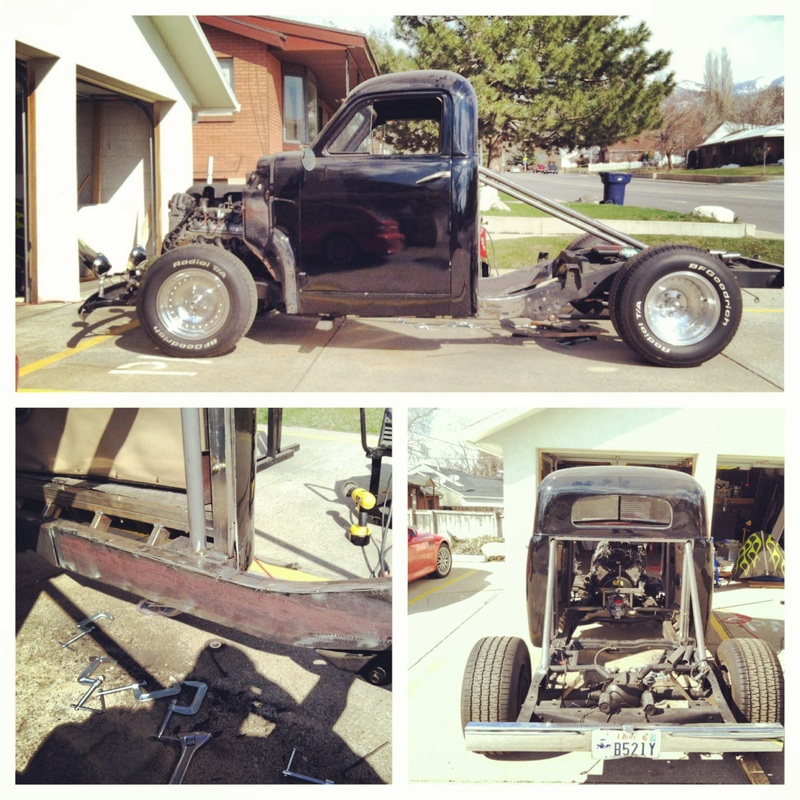
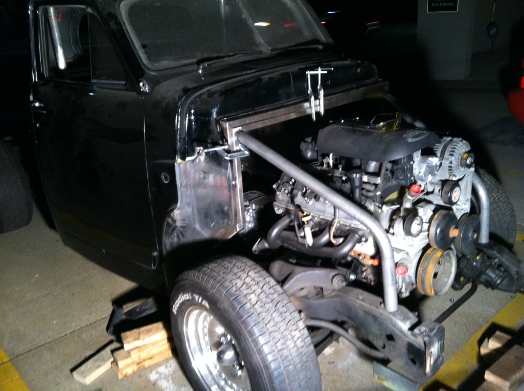
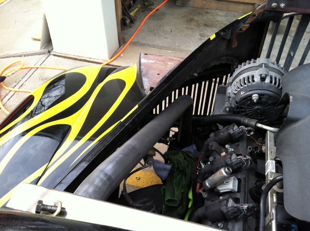
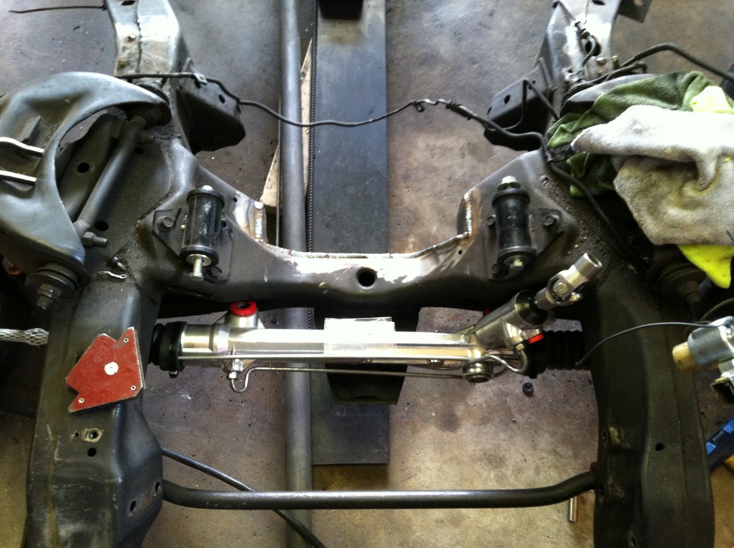
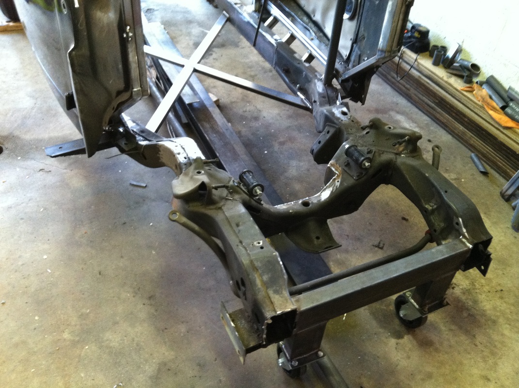
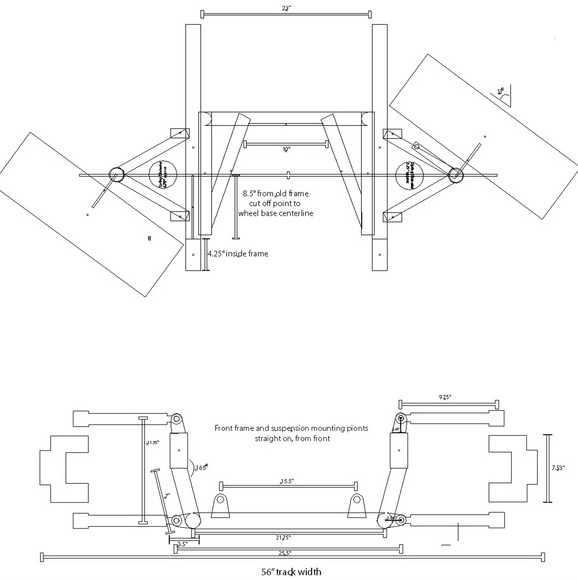
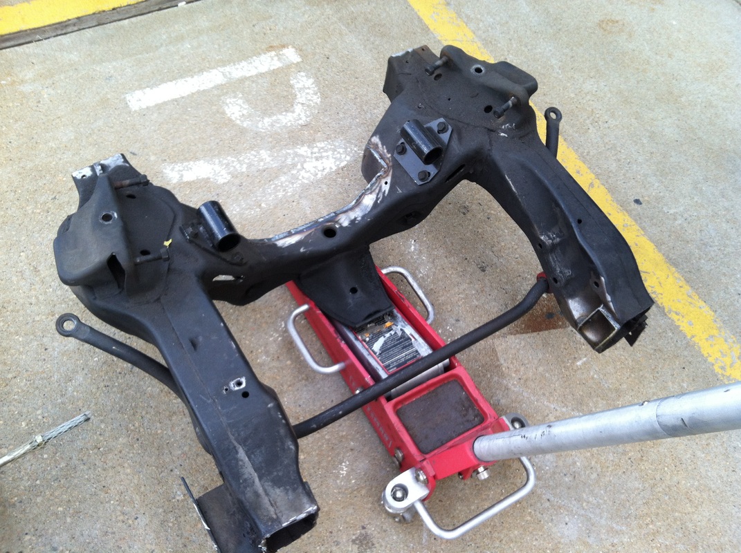
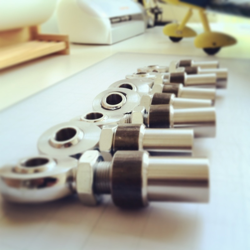
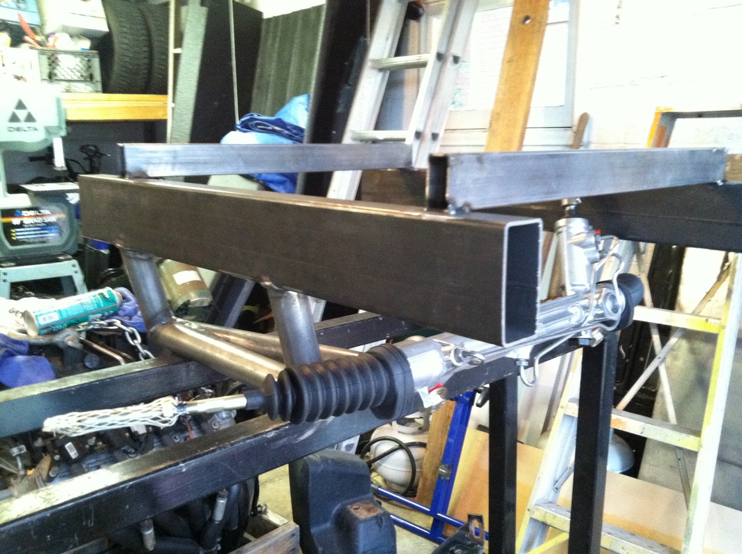
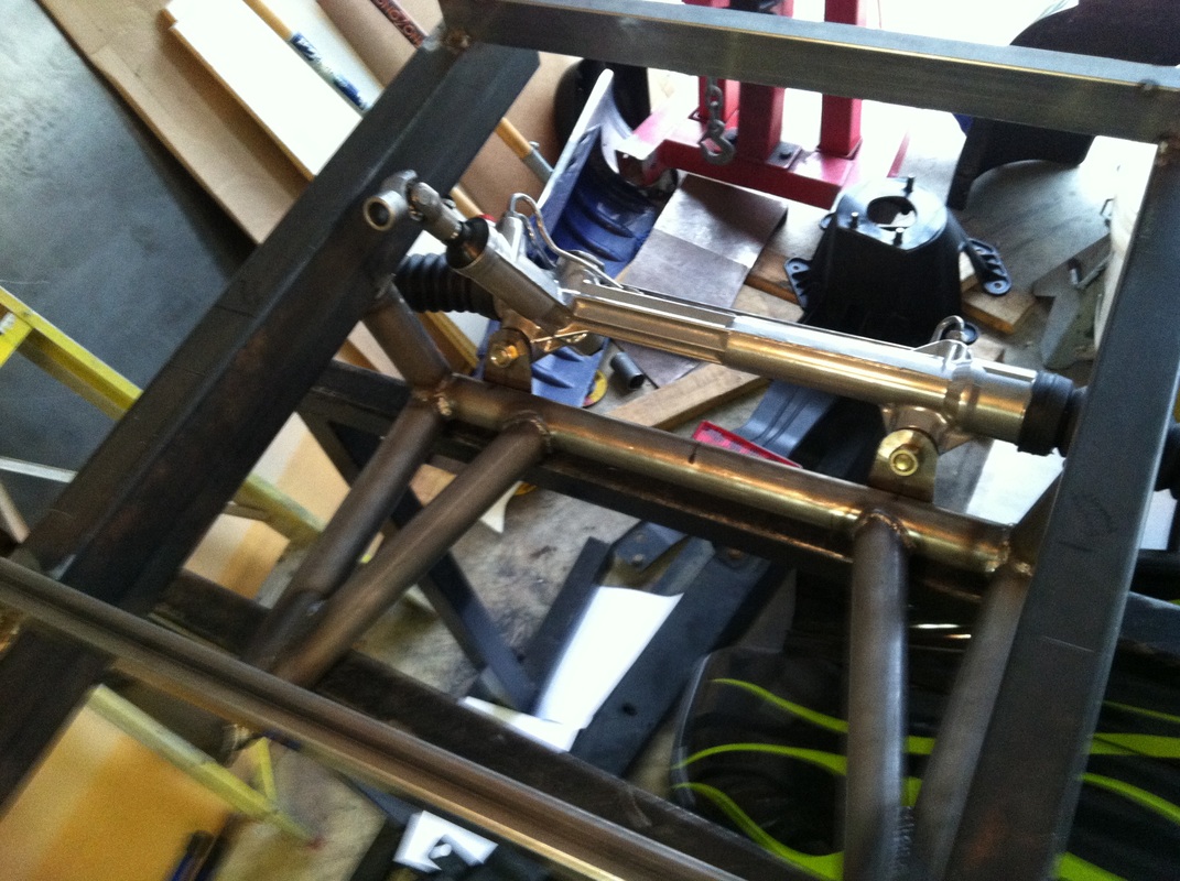
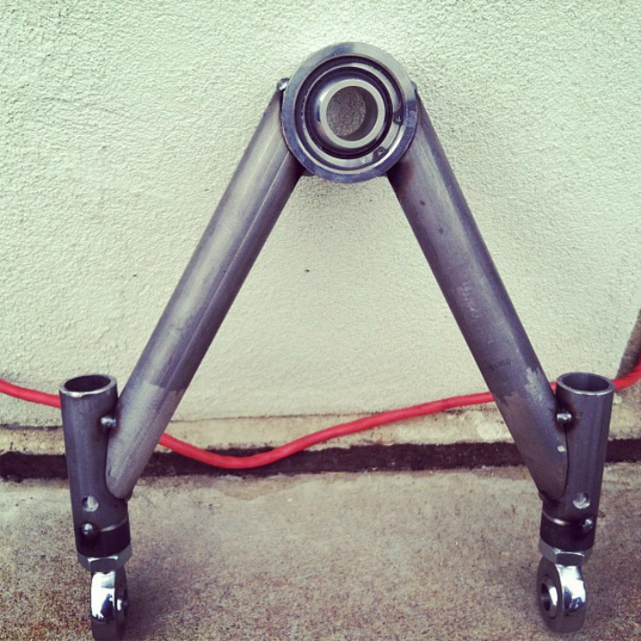
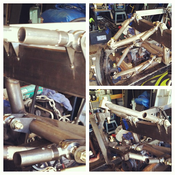
So in my last update, clear back in April this year, I left you here: I had just cut and shorted the frame, welded in the boxing plates and some chassis bracing, and then fit the rear parts of the roll cage. Oh yeah and I had cut my finger on my saw... The next thing on the to do list was to sort out the front sections of the roll bar, going from the main windshield hoop, out of the firewall and down to the frame. I wanted to do these in one section of tubing, which meant to clear everything properly had to bend each side in 3 different spots, on 3 different axes. Happy to report I only wasted one section of tube here. At this point I decided that I wanted to bring the engine forward about 2.5 inches so I could put in a flat firewall, rather than the recessed one I had made previously. in order to do that i needed to take some material out of the S-10 cross-member. Also at this point I decided that it would probably be a good idea to figure out how I was going to build the front suspension and steering mounts. After many hours spent pondering how I was going to fit it all I decided the simplest way would be to build it all from scratch. ...Well that was the theory anyway. I started to draft some rough plans off of some measurements taken off of the existing frame to give me a fairly good idea of what I was going to build before I built it. The main goal I wanted from the suspension was steering angle so that is what I started designing around. The secondary goal to the suspension design was equal length and parallel A-arms. My third goal was to make it all adjustable. I wish I could tell you that I wanted the secondary goal met because of my advanced knowledge in the world of suspension design, but the truth is I have skimmed over a few suspension design books, and I am an insurance salesman... not an engineer. While I do understand the basic principles and the pros and cons to each I decided to stick with it. Worst case scenario, I don't like it and have to build it a different way. Onto the fabrication of the front suspension: First step was to cut off the old front frame and all of its suspension mounting points. I planned to used 2x4 square tubing, which would slide into the old frame at the cut off point, and when I did the final assembly I could weld and brace it so it would be plenty strong. Next I savede a little money, and bought some hiem joints, thick wall DOM tubing in two diameters, and some 2x4 square tubing, and a crap load of laser cut brackets... Side note here, I found a sweet little motorsport supply store in Salt Lake that had everything I was looking for, which is awesome because I hate ordering things on the internet. The place is called Midnight 4x4, check out their website here: http://midnight4x4.com. They had it all in stock and for the same price or slightly less than I could order it online. I started making the new sub frame first. That is 1.75x .120 wall DOM and 3/16 - 2x4 tubing. Notice how the rack was mounted out in front of all this... more on that down further. By the way, doing steep angle notches is a pain, and cannot be done with cheap tubing notchers. but I found a cool program, that will print out traceable patterns to scale, and then you can use a cut off wheel and a grinder to make them. Here is a link to one of the few programs out there: http://metalgeek.com/static/cope.pcgi. Next I made a quick jig for the arms per my plan measurements and started notching the 1.25" .120 wall DOM tubing. because the angle was too steep for my notcher again I used the software printable versions, and as you can see all the fit ups are nice and tight. I also decided to go without ball joints and use a Uniball Set up on each arm... My reasoning? well, I couldn't find the proper ball joint plates for the top arm that would allow me to get the angles I wanted and these will be stronger anyways. I bought all 4 of them in a kit and chose 5/8" high misalignment spacers for the top arms and 3/4" for the bottom arms. I also drilled out the arms to accept straight bolts instead of tapered ball joints. sorry for the crappy cell phones pics... but hey, sometimes that's all I have with me. Here are all of the arms tacked together and mounted in the tacked brackets and with the spindles installed. Remember how I was going for a parallel and equal length set up on the A-arms? Well I had to change that. One thing I didn't account for when designing the front suspension was that the spindle I was going to use from GM already accounts for a shorter top arm. When I first mocked everything up I noticed that there was way too much positive camber that could not be adjusted out with the heims. The only solution, which didn't include making my own spindles, was remaking the top arms so they would be 1.5" shorter and then mounting the top arm a little more inward on the frame. I am happy to report that it worked, and only sacrificed a little of the original design. Part two of the Drift Stude update still to come...
2 Comments
8/3/2014 11:10:54 pm
Reply
Leave a Reply. |
Download the
following Designs used in this build: Archives
February 2018
|
