|
So... right after my last drift Studebaker update I was planning on uploading the second part but had a major malfunction in my external hard drive, which had over a Terabyte of pictures and videos. All of the pictures I had planned on using in that second post were lost. So I will attempt to give you the final part to that update with different pictures, but also update you on the progress this weekend. 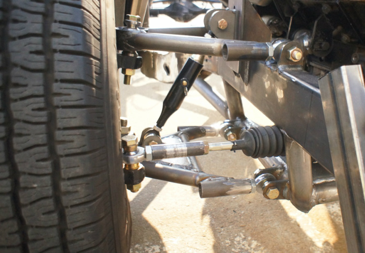 In the last post I left you with the arms mounted to my new front sub-frame, but mentioned that I would have to shorten the upper arm and move it inward. here is the final arm set up, still parallel but the geometry from the spindle corrected. 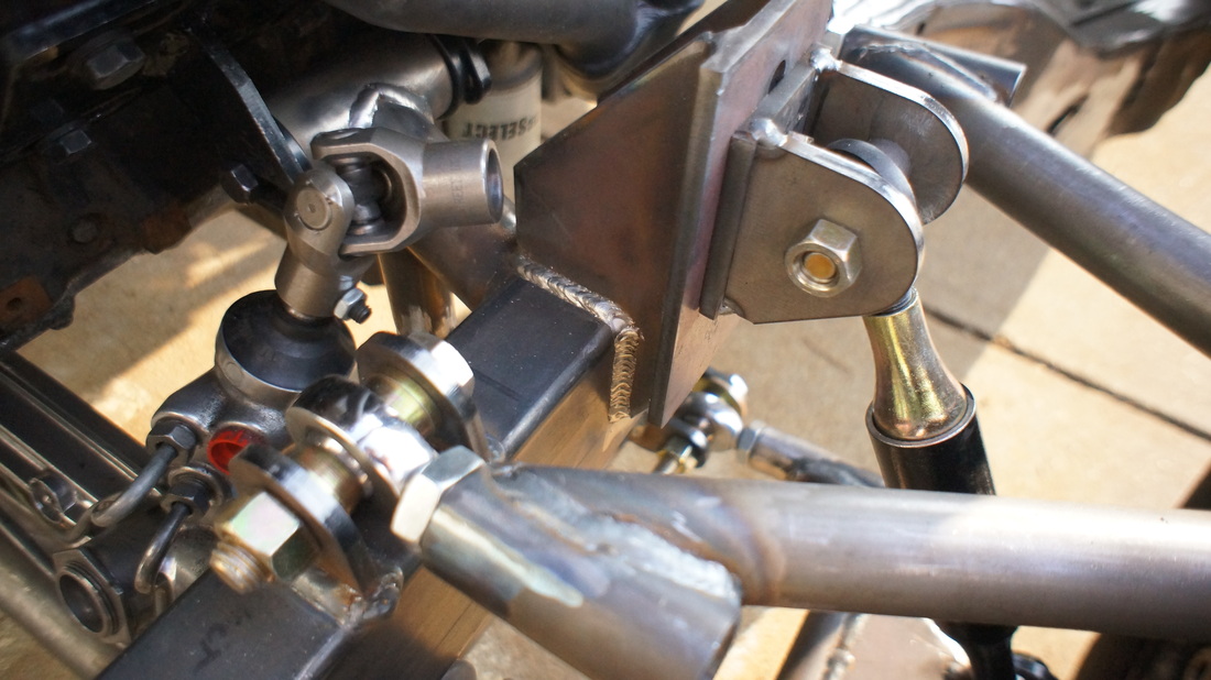 I also had my buddy Nick cut out some brackets on his plasma table, which I had designed on my computer in Adobe Illustrator, then saved as a DXF to cut on the plasma. I don't have any CAD software but I do have a lot of graphic design software which is basically a 2-D version. It worked amazingly well and they cut out perfectly to size. I wanted the ride height to be adjustable, more so than the few millimeters that I would get out of the coil-overs, so I made the upper shock mount adjustable within 4 different holes for about 4 inches of ride height control. Until I buy the coil-overs I wont do the final welding on the coil-over brackets, just to make sure they are the correct width. My shock mock up tools from Speedwaymotors.com came in real handy here, though they did require some trimming to get them down to a more manageable size for my suspension. 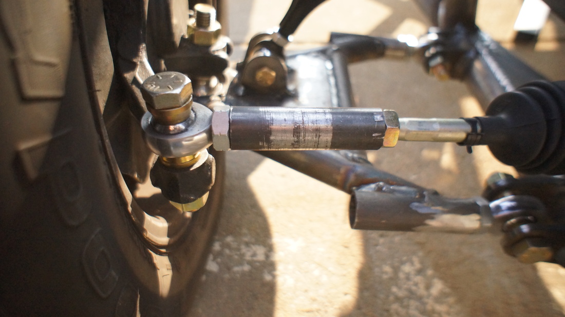 One of the bigger challenges with the front suspension, believe it or not, was finding a good way to connect the steering rack to the steering arm on he spindles. The rack has a weird thread size that many Ford tie rod ends will fit, but each of them would have thrown off the parallel geometry with the steering arms. If it is parallel with the A-arms it will help reduce bump-steer. In the end I decided to make a right hand/left hand threaded tube out of very thick wall DOM and use a hiem in place of the tie rod ball joint. Again it was a bit of a challenge because of the weird thread size on the rack. so I had to thread the heim side as a 5/8, and the rack side as a 9/16, and alternate between right hand and left hand threads. I am happy to report that it worked after I found a place in Salt Lake that had the appropriate drill bits and taps for the weird sizes. If you are close to salt lake and need awkward sized in taps, or other machining tools give Paxton Production Tools a call. 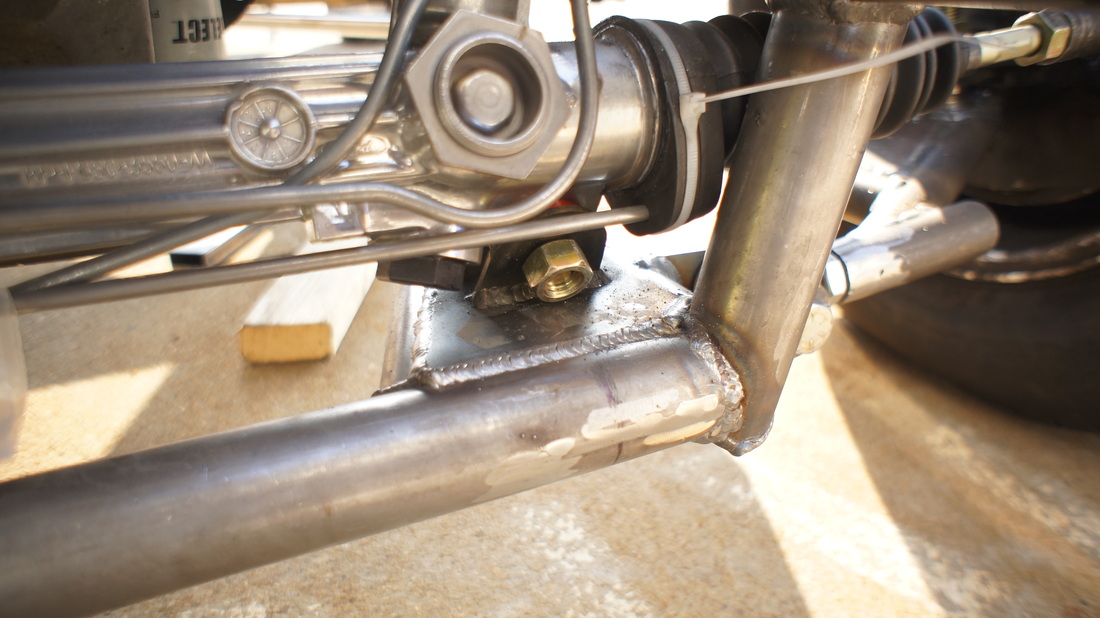 Speaking of the steering rack, I forgot to mention after hinting at it in the last post that I change the mounting point from the very front of the sub-frame, to just inside. It is mounted to 1/8 plate welded over the tubing on the frame at the angle you see in order to have the steering linkage clear the engine mounts, and the headers. Yup the bolts I bought were too short, but don't worry they will be changed out. 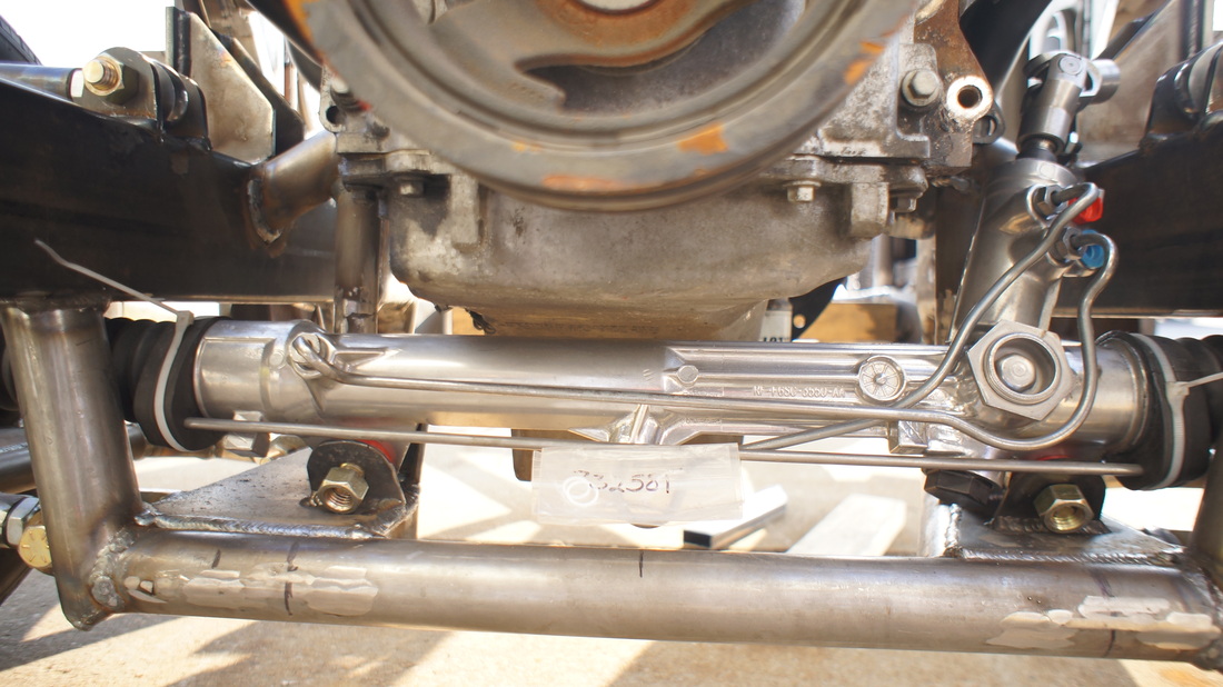 Here is another shot of the rack. As you can see there is about an inch between the oil pan and the rack. This is a result of a test fit of the engine where I realized that the engine mounts made it so the pan sat right on the rack, which is no good. The mounts came out, were remade and then put back in. Now the engine fits like it should. 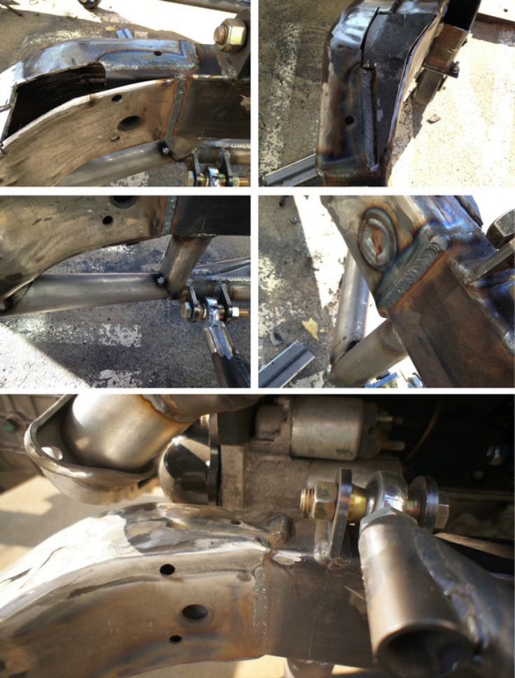 Now that everything is fabbed and fit, it was time to put the sub-frame back into the main frame. The 2x4 square tubing was used in the sub-frame on purpose because it slides into the existing S-10 frame and will add some extra strength when it is all back together. You can see, starting at the top of the above picture, the process of welding it in place, then cutting and fitting the new pieces, and the lower tubing support that again adds a little bit of strength to the new sub-frame. Since I don't have a frame table it was a bit of a chore getting it all square. I purchased 4 screw jacks from the local junkyard for a total of $11 and once the frame was level in my driveway using those jacks I used a plum-bob to mark the the center of each wheel mounting surface on the ground. Then I proceeded to measure the marks: the width between each, the length between each, and the diagonal length between each. All said and done the closest I could get the new frame was within a .25 of an inch of square without adjusting any of the adjustable parts. But with some slight adjustment to the heims on the a-arms of the driver side I was able to get it square, and then welded it in place. 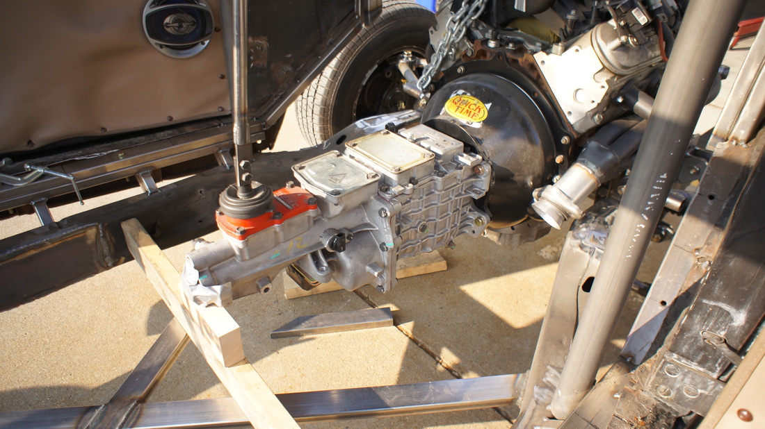 Next onto the transmission mount. I wanted to make something removable so the trans can be removed easily if needed. 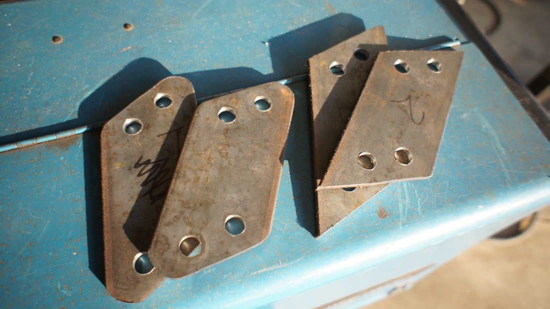 I started off by making a few brackets out of 3/16 plate. 2 of which will be welded to the X Brace on the frame, and the other two will be welded to the trans crossmember. 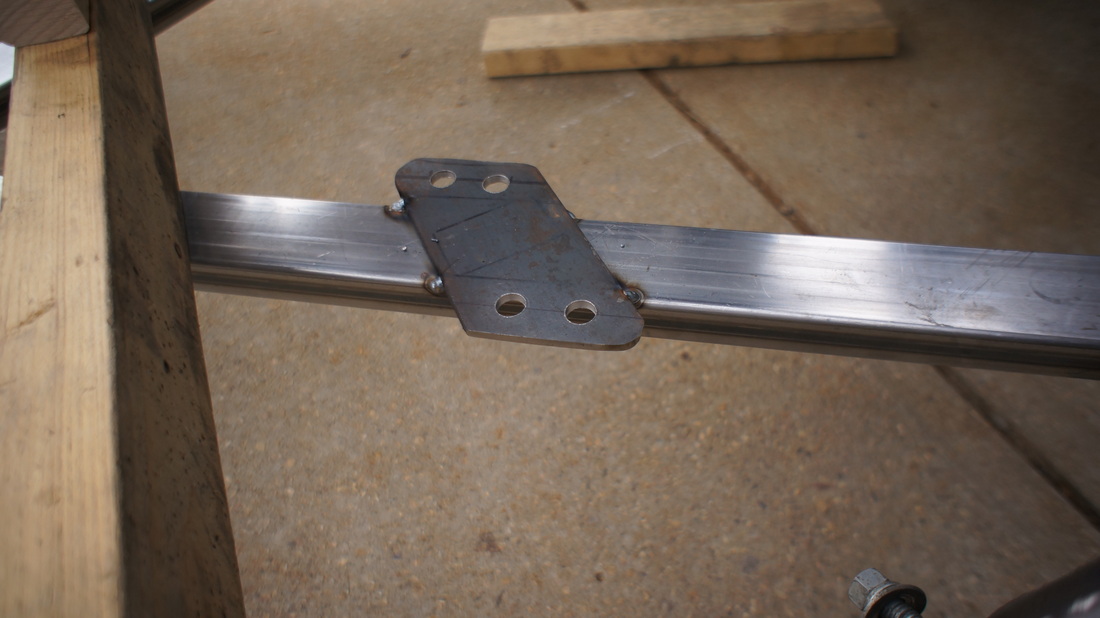 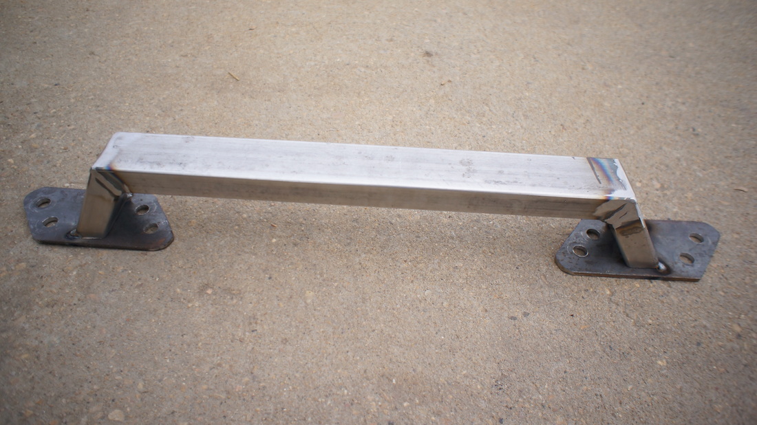 Then I made the actual crossmember out of 2x1 14ga. square tubing. 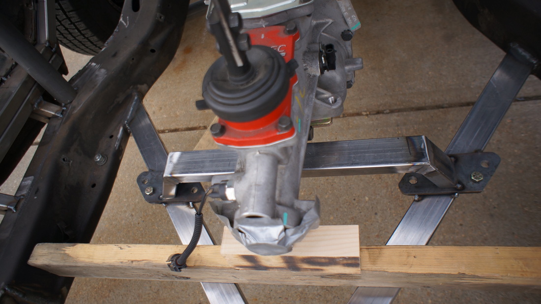 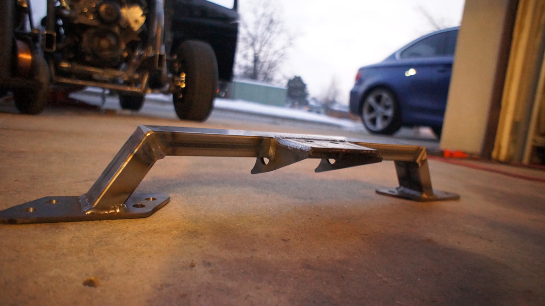 And finished it off with more 3/16 plate for the mounting point on the transmission. 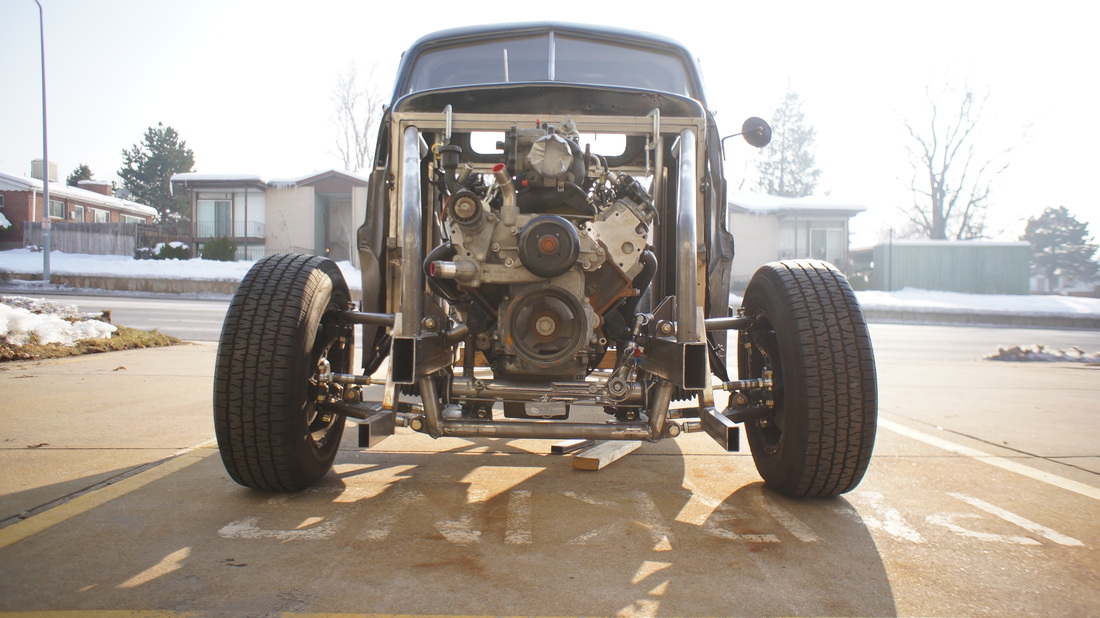 And lastly before the temperature dropped below 20 degrees I lengthend the front roll par supports to mate up with the new sub-frame.I used 1.5 inch DOM as a sleeve inside the 1.75 DOM in order to keep the strength up in the spliced sections. 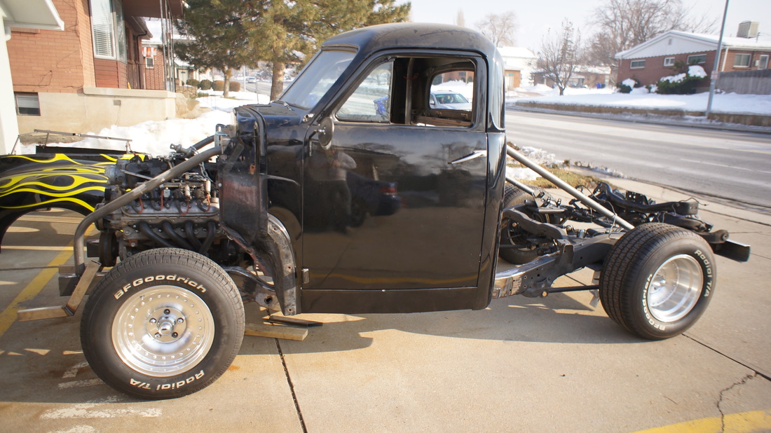 This brings the Drift Studebaker build up to date as of 12/28/2013, and as long as there are some semi warm 30 degree days I will be updating you more regularly throughout the winter with the building of the floor, firewall, pedals mounts, and steering wheel column and mount.
1 Comment
|
