|
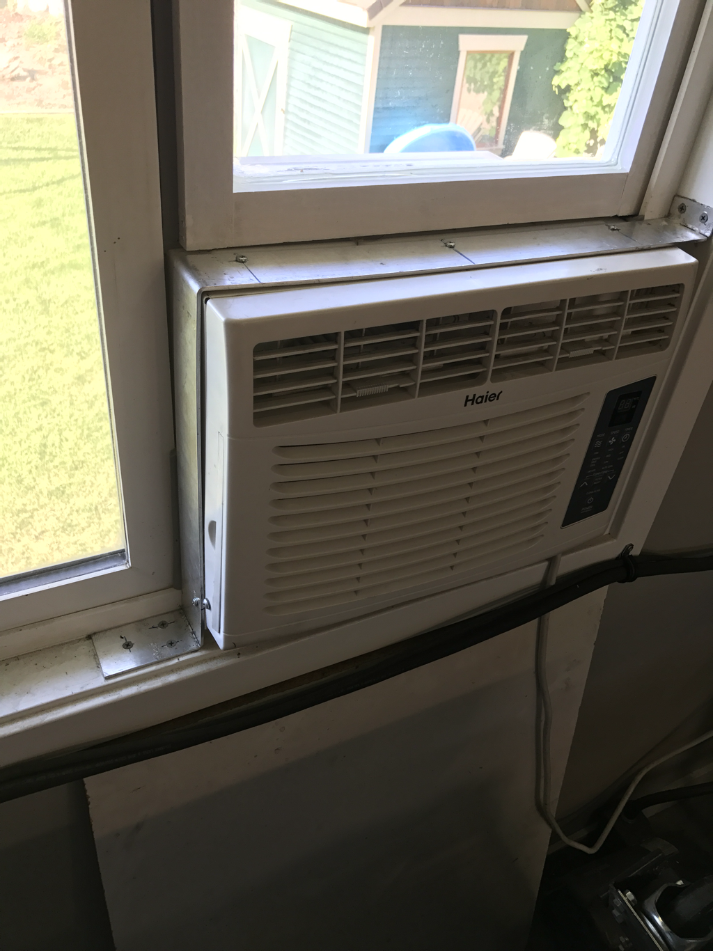
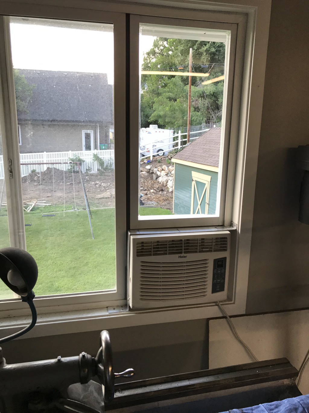
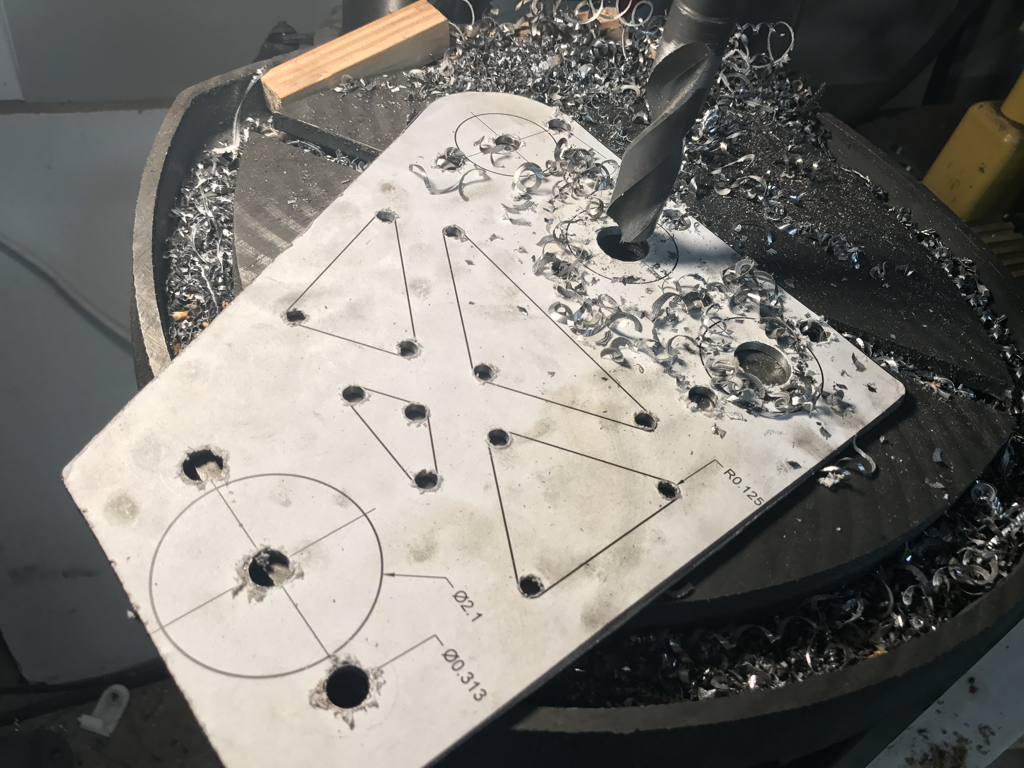
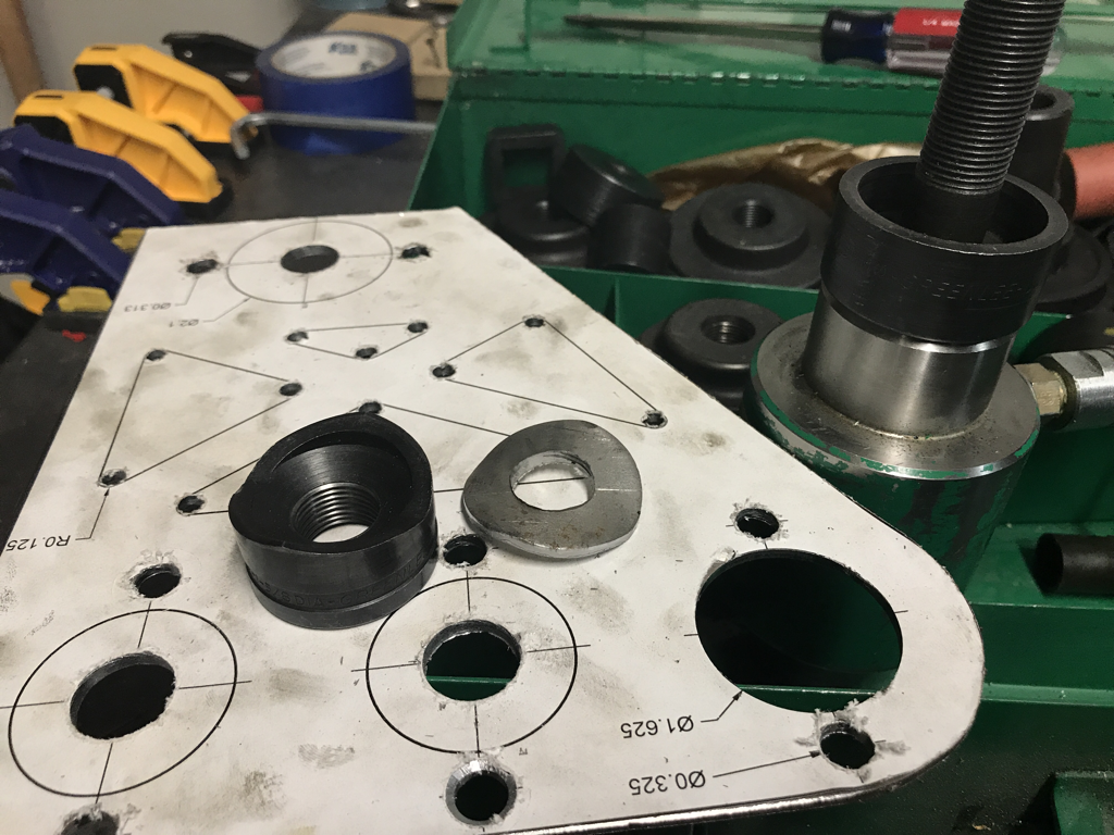
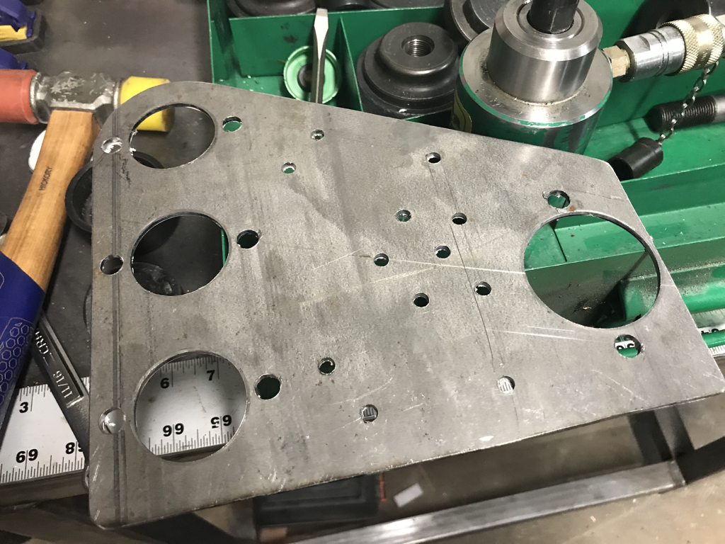
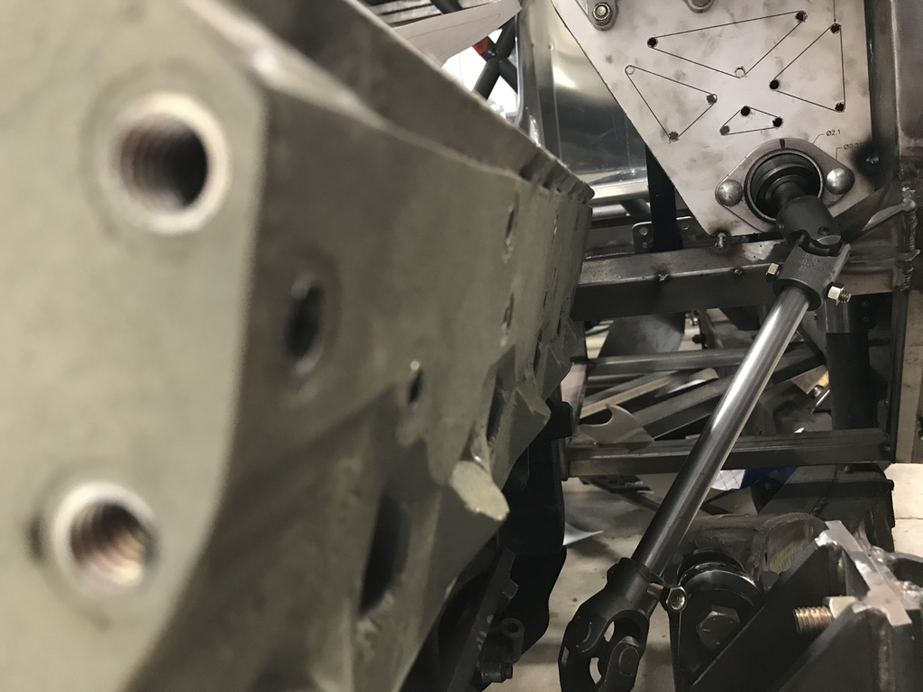
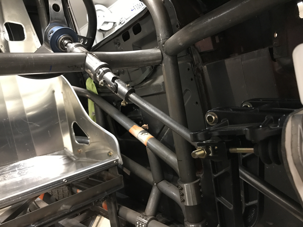
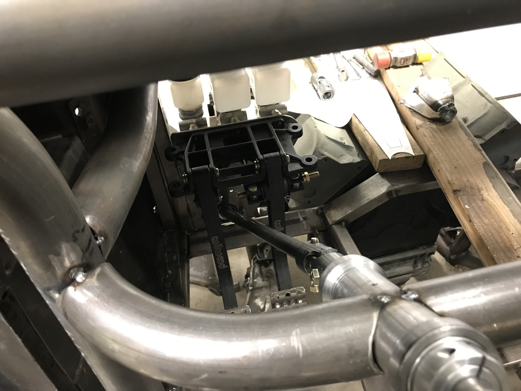
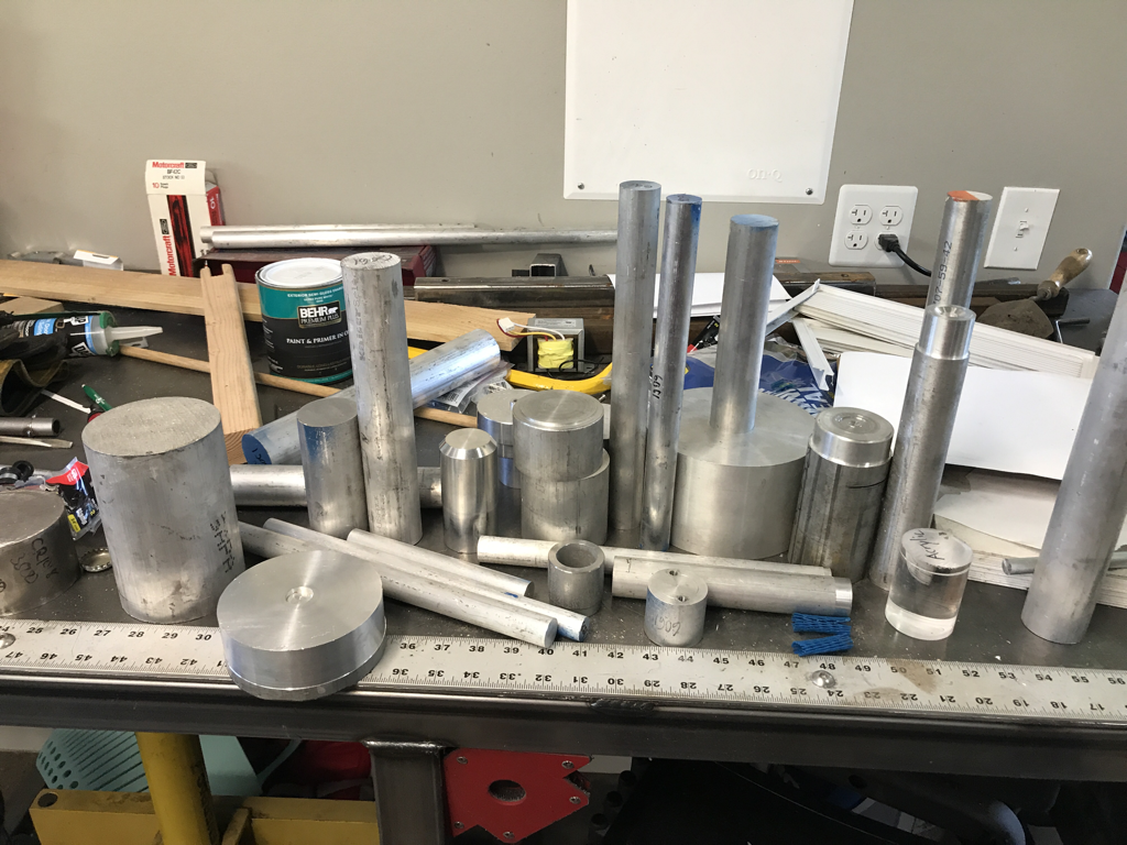
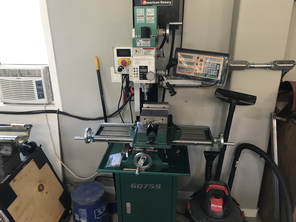
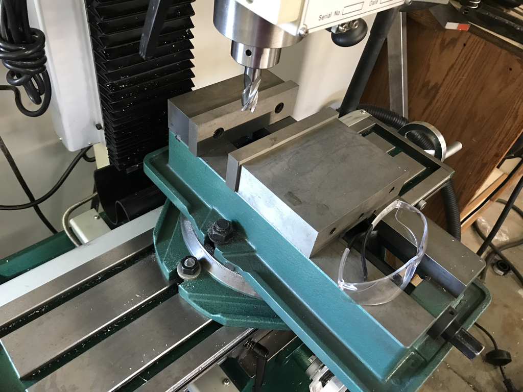
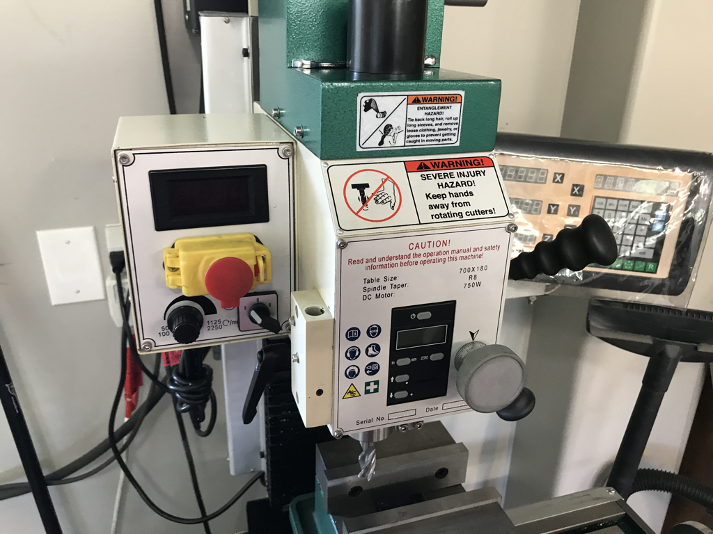
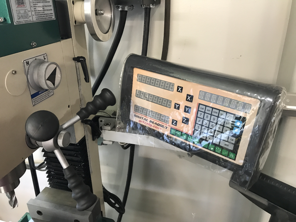
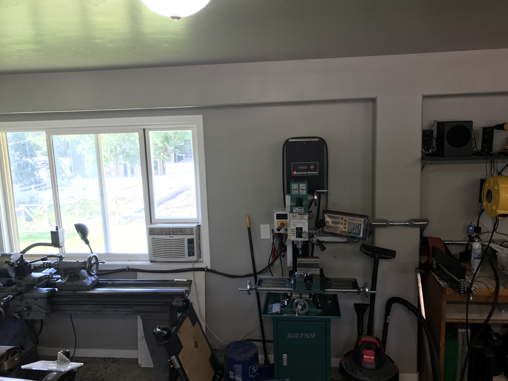
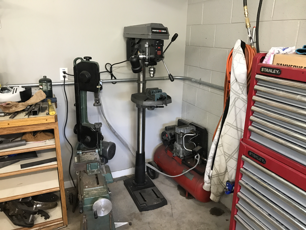
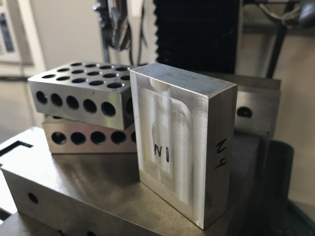
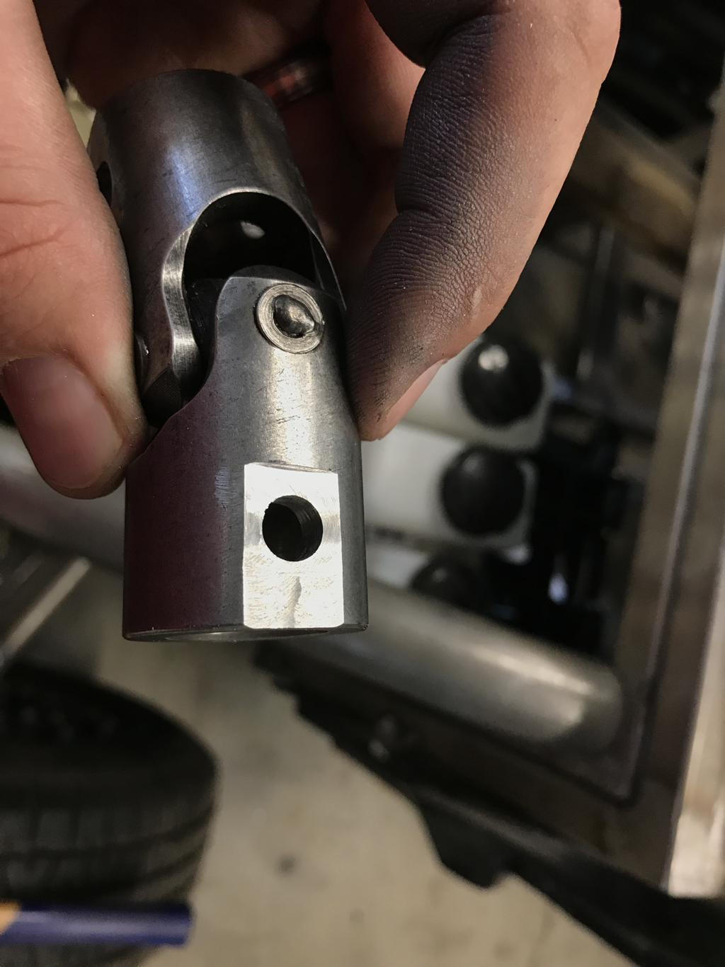
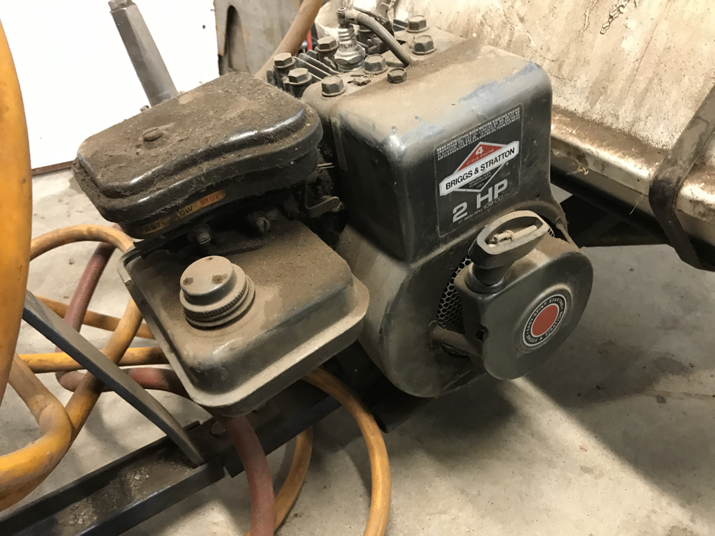
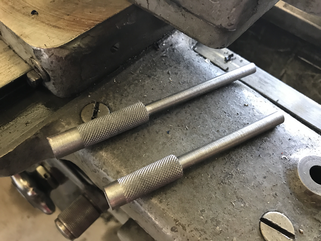
First things first, it was getting pretty hot here in Utah come the end of June so I had resolved to put in a little air flow to the garage via a windo air conditioner unit. I was able to get this one for nothin, as it was my sisters old unit she had had in an old apartment. I whipped up a quick aluminum strap from scrap and screwed it down. Next up I had to spend a bit of money and build a window frame. My wood working skills are far from good, so I opted to build a frame for a single pane of glass, my mortise and tenon joints sucked, so i opted to just to flat cuts and glue 3 sides and screw in the 4th so I could set the glass in a recess before final assembly with some clear cault to seal the glass. Overall it didn't turn out half bad, and some weather stripping helped seal all the gaps. now that the shop had a little air flow in the 100 degree temps it was time to get working on the relocated steering colum. I had started redesigning the mount for the colum and pedal assembly in Fusion 360 in the last post as seen here. Rather than calling up my buddy to plasma cut a single part, i opted to do this one the semi old fashioned way by printing out a 1:1 scale paper template and transferring all of the elements to a plate of steel. This was accomplished by gluing the paper to the metal, cutting the outside shape on the band saw, center punching each radius, then drilling the appropriate holes. The big circles were drilled to .75" to fit by knockout punch set. The lightening triangles in the middle get the radius corners drilled and then the ill finish the cutting with a die grinder. Overall this makes for a pretty accurate bracket... here is the knockout punch doing its job. This plate is .125" thick and its about the limit for the knockout dies. But its a hell of a lot better than trying to use a hole saw or a huge drill bit. Here is the backside after all the holes had been punched. Ill finish the lightening triangles in the middle if everything works. From printing the paper to this point took about 40 minutes which is worth mentioning, because there was a point where this would take me half a day... it helps to have the right tools. Here is the new mounting plate tacked in, as you can see, when comparing the old version to the new, this eliminates a couple of universal joints, and the hiem joint, and it looks as though I will still be able to sneak some header tubes down there. Here is the straight on view, it helps to verify that this was the right move as far as space for the headers. The other bonus with this new mounting position was that I was also able to eliminate another universal joint from inside the cab. Here is the view looking down. The angle was nessasary so when it went through the firewall there was enough room left for headers. In Mid July I made a scrap aluminum purchase from one of my clients who was closing down their research and development lab. It's kinda crazy but these guys ran an R&D lab dedicated to developing hydrogen fuel cells and alternative energy things, but in reality they are a very clean, very accurate, and very complicated fab shop. I wish I could have purchased more, but I got a pretty good deal on all this, mostly 6061 aluminum some 4032, from .25 rod up to an 8" diameter piece. Now ill just have to figure out some cool stuff to build out of it. And now for the most exciting tool purchase I have made in a long time... that's right I now have a milling machine! I have been watching our local online classifieds pretty closely for about 6 months just waiting for the right deal to come along (and also at a time when I had money available). Early on I had come to terms with the fact that a Bridgeport or Bridgeport copy were going to be too expensive so I was keeping my eye out for smaller bench mills. This one popped up about a week back and the price was right and it was nearly new. I have never owned any grizzly products, but there is a ton of information about these machines online and lots of happy customer reviews. So far I am extremely happy. And maybe one day i will convert it into a CNC. Some of the features that made this one desireable was the DRO, variable speed control, and the included base. Brand new this one goes for $1800 ish plus shipping. I managed to get it here locally two years old, with a vice, and collet set for $1295. It was so knew the guy had only used the drill chuck and had never taken the vice out of the box. Realistically the vice is huge for this mill, but ill use it for now and get a smaller one in the future. here is another shot of the vice and bed. I did have to purchase some t-nuts and end mills, but going down to Paxton Supply in Salt Lake is always fun. I opted for a handful of different sized carbide end mills. The one chucked up now is a 5/8. As i mentioned before its a little big, both in height and length, so it takes away about 3 inches of usable Y travel on the bed so smaller vice will be purchased later, but probably not until this one caused problems with a job. I already have a set a parallels, but a dial test indicator is coming along with some edge finders and a new dial caliper. The rest of the tooling I will buy on an as needed basis. here is a shot of the speed controller on the left and the quill control in the middle. This one also has a DRO on the quill along with the main DRO. Here is the 3 axis DRO panel. And you can also see the quill lever, and the gear box speed selector. I think the low gear gets you up to about 1300 rpm at max speed and the high gear gets you up to 2200 rpm at max speed. The DRO is going to be very useful, and now I wish I had one on the lathe... but that's another $3000 so it will have to wait until much much later. You cant really see it because of the glare on the plastic protector, but it does have a couple handy program buttons, to help you layout holes in various patterns. I opted to put in where the drill press and 10 ton press had been. This way it had enough X axis travel, and putting the vacuum next to it will help to keep the chip mess to a minimum. the drill press is now in the corner with the band saw and air compressor. Where the welder was. The welder is moved around so much i figured I'd just leave it out and move it where ever, since it is one of the easier pieces to move around when needed. The only think i have yet to find a place for is the 10 ton press. Right now it is stored under the metal work bench. I'm thinking I will mount it on top of the workbench and scrap the stand it was on, but Ill worry about it later. First project on the mill was to tram the head, then tram the vice. Once that was complete it was time to cut some stock and see how square I could get it and what its capabilities were. I am happy to report it trammed up easily and even with my amateur milling skills i was able to square up some stock really well. The finish is nice and smooth too. Man I love this thing. For the first real job I decided to give the universal joints used in the drift Stude steering some flat spots for the bolt heads and nuts to sit on when its all tightened down. I'm not sure of the material on these things but its harder than your average mild steel, but it went well on the new mill. The same week I purchased the mill my grandpa called and asked if I had any use for an old Briggs and Stratton motor that was powering an old sprayer. I of course told him him yes and went a picked up the sprayer. I plan on junking everything but the motor, the cuppler, and pump. And i will use the motor in a future project at some point. The one I have in mind is a powered wheel barrow to help with the yard. More on that later. And last for this update is a little side project that goes hand in hand with the new mill. I am going to start teaching myself how to be a better machinist and the best way to do that is to try and make some stuff. First up is a simple machinist clamp. Today is July 30th and I am trying to post once a month now, so I thought i would show the progress so far since I won't have a chance to come back to it until August. These are the two screws that goin in the clamp. These were machined down on the lather from .75" stock to .5" on the knurled part and .3125" on the smaller shaft which will get threaded to 5/16X24 fine threads. The knurled part will also be cut down later after all of the lathe operations are complete. It will also involve some milling but I that will have to wait for next months post. If you want to see the recipe I am following for this project, you can visit This video on YouTube put up by Mrpete222. He does excellent videos and most have to do with machining. Go check him out. For now the drift Stude project and other garage projects are up to date as of the end of July 2017.
0 Comments
Leave a Reply. |
Download the
following Designs used in this build: Archives
February 2018
|
