|
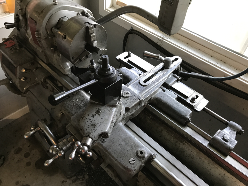
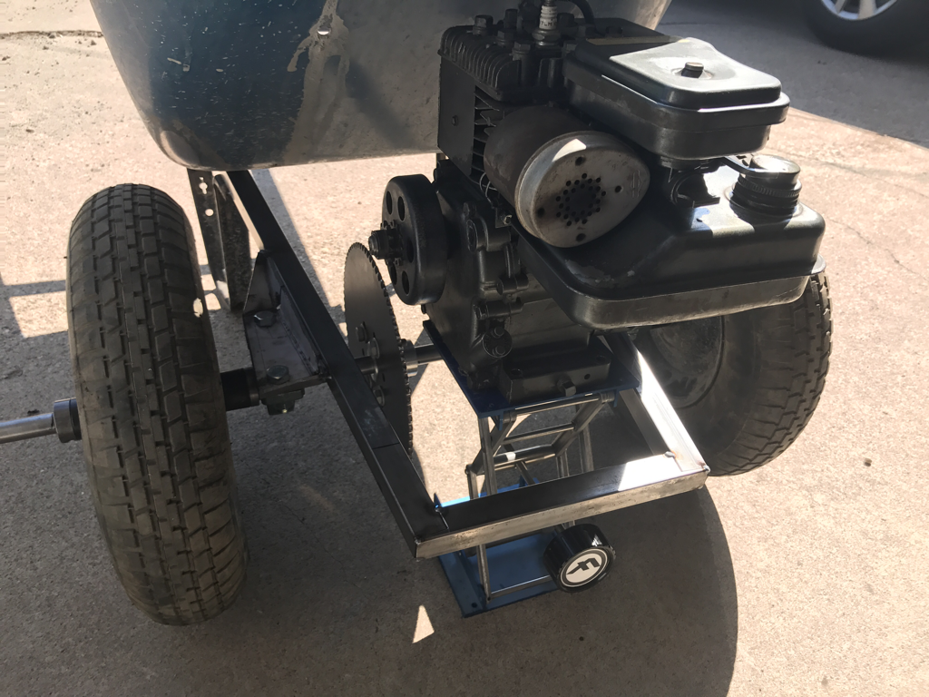
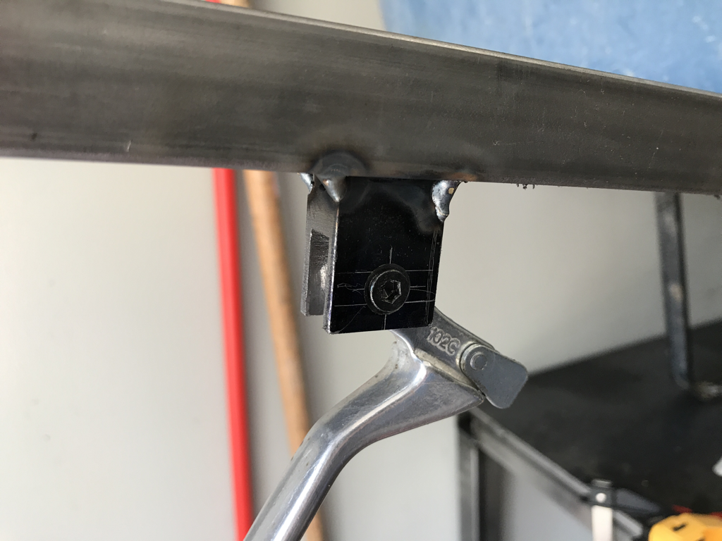
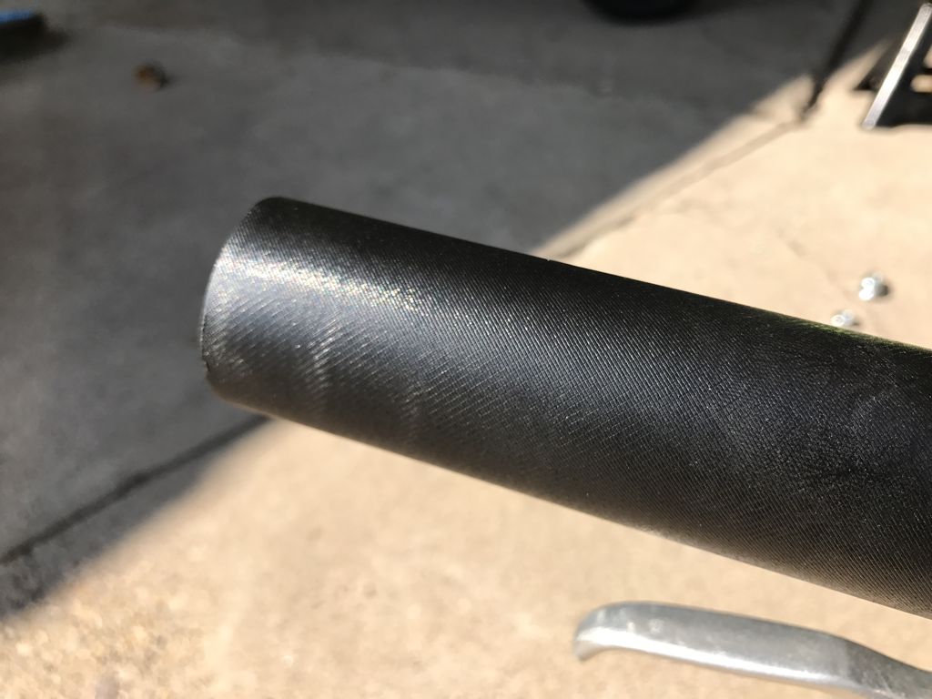
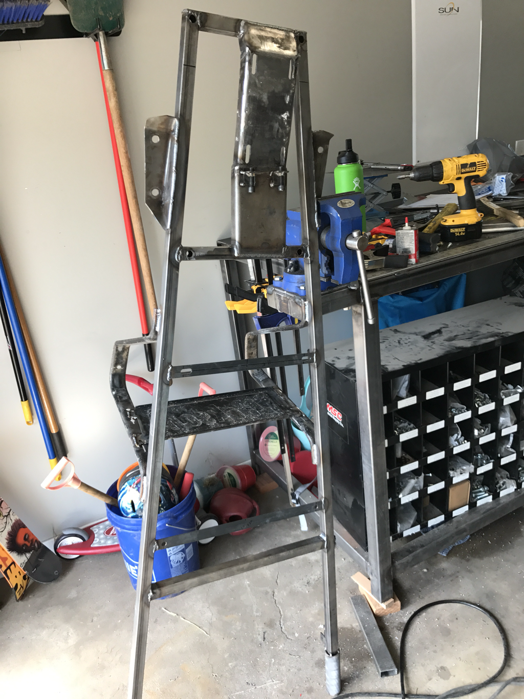
Well... Here is it mid Sept and I have finished a project. Sadly it is not the Drift Stude, and you will have to settle for a finished wheelbarrow instead. Though this means, and I am promising here, that I will do some much needed drift Stude work now. I left you last in august doing some keyway broaching on the bushing inserts for the wheels and with the lathe apart for cleaning... The cleaning went well and I managed to free up the taper attachement, just in case I ever need it in the future. I left the old cross feed screw and nut in there, but plan to replacement in the near future when my wallet will allow. With everything cleaned and oiled it was time to get moving on some wheelbarrow parts. first up was the hub for the sprocket. This like the hubs/bushings for the wheels needed to have a keyway cut, but also was a bit more complicated because it needed to have a bolt circle drilled and tapped and as well. It turned out really well and the only problem I really had was cutting the aluminum slug down to size after the first machining process. The bandsaw for some reason didn't really like this big of a piece of aluminum... One other slight problem I had was with the bolt circle. The DRO that came on my mill has a bolt circle function, but I found out when I went to go use it on this that some fo the buttons on my DRO do not work. Namely the equal button, which is needed for the bolt circle function and also some of the other functions. I will have to address the DRO issue later, but for not it worked to pull dimensions off of a CAD drawing I did for the part and use the functional scales part fo the DRO to dial it all in manually. The end result was the same and worked great. I also managed to get some cool time lapse footage of the lathe machining below next it was time to build a new frame. The old wheel barrow frame was a bit rickety and warped, so I opted to take some 1x1 18 ga. Square tubing I had laying around and put one together. I traced the wood frame on the garage floor, and laid out my tubing on the lines and tacked some supports to it so I could cut some cross supports. I managed to do a nice miter on the front bar. I also decided to reuse the bottom rest supports as they were nice stamped metal pieces and I didn't want to waste time making parts that I didn't need too. now that the frame was ready it was time to design some brackets for the pillow block bearings that would hold the axle. I whipped up a quick design in fusion 360 after a quick learning session on their new sheet metals module. Once the design was done I used the software to flatten the pattern, printed out the flat pattern. Once printed I glued it to a piece of .125" sheet, cut it out on the bandsaw, drilled some holes and bent it up using my press brake, and my bench vise. The latter being used as my press brake is not a finger press brake. Overall I am really impressed with the sheet metal tools in fusion 360... I definitely need to fine tune some of my sheet metal rules for better gaps, but also some of the error could be in the crude bending using my bench vise. Once they were all bend up I bolted the bearings onto them and tacked them up on the frame. here is the end result testing the bearings, wheels, brackets and hubs all together it was also useful to test the motor placement and bucket placement too at this time to double check that the plan in my head was going to work. I also found Avery useful purpose for the scissor lifts that I got form my client when he closed his business. This was also useful for finding out where the keyway for the sprocket hub was going to go, and I used this set up to mark where the sprocket would be on the axle for machining the keyway. before I got the engine mounted I figured it would be a good idea to cut the keyways into the axle. This is something I have never done before, so I figured I would do some tests, to see how deep of a cut I would need for my 3/16" keyways. The test piece is shown above. Now to cut the keyways on the actual axle. for this I used a pair of V Blocks on parallels in the vice and pushed the axle into them with the clamping force. I'm not sure if this is the best way or correct way to hold an axle while cutting keyways, but it seemed to work well for me. In all I cut three, two on the ends for the wheels, and one offset to one side for the sprocket. Also, you cant see it but on the long side of the axle hanging out of the vice I used my other smaller scissor lift so it had some support. Here are the shots of the completed key ways in the middle for the sprocket. I am please with how these turned out. Side note I found that cutting the keyway about .025 deeper than the actual keyway depth needed was the way to go. It still left a really snug fit, but did allow it to be slid to the right spot easily for fine adjustments. After this step was done I slide the wheels on the axle as well with the key ways in place so and tacked them into place on the rims. Of which I forgot to get pictures. witht the keyways cut it was time to get the motor mount worked out. For this I had a rough Idea worked out in my CAD model but wasn't really sure how it would work because I had used some other peoples models for the engine and bucket part. And they weren't true to the dimensions of what I actually had. But the frame in my design and axle assembly was as well as the bolt pattern in the model for the motor mount. So I printed it out and glued it on to a piece of .125" plate. I drilled center holes on the drill press, and then clamped the plate in my vice on the mill to cut the slots. This did not need to be very accurate as the slots were purposefully oversized to account for adjustments in the motor for the chain alignment and chain slack take up. The paper pattern was also used to put a couple fo rough bends in the plate to make sure the motor was level when installed on the frame and it was at rest. The actual milling went pretty smooth. I simply lined up the ends mill with my drilled holes and then worked it one way and then the other. On the first cut I wasn't sure if I could do the entire cut all at once so I started with taking about .035" depth of cut and then worked out that I could in fact push the machine a bit and take the entire depth all at once. you can see above that the motor mount worked out well enough, sure its a little rough but it will get the job done, it just wont win any prizes for beauty. With the motor mounted it was time for a quick test run. The engine fired right up as expected, and the tires spun as expected, just in the wrong direction. I hadn't really checked the engine rotation when I got it, but it was mounted in with the muffler pointing forward on the pump sprayer that it came off of so I had assumed that was for forward rotation. While it was on that sprayer, the engine only powered the pump and not the wheels, and I should've known better. But hey you live and you learn right? All I needed to do was cut the tack welds on the motor mount and switch it over to the other side, and flip the axle and turn the motor around. All in all the fix only took about 35 minutes. with the engine orientation corrected I could move onto the throttle controls. I decided it would be easiest to use a barker lever from a bicycle and cable for the motor with a series of springs to help return the throttle to idle. The only part I had to fab up was something to hold the brake lever which was a quick job on the mill. The bike lever came off of a $10 bike from a local thrift store. The cable was purchased new from a local bike store. I also cut the cable stays from the bike frame and welded them to the wheelbarrow frame for some fancy cable management. I also fabbed up two new tube stays on the lathe. as you can see I managed to correct the wheel direction, and you can also see the throttle cable in action. With its return spring setup. At full throttle there is a bit of wobble and unbalance from the wheels, but at that speed you would be sprinting behind the thing, so I am un-concerned about it. during the test run I noticed that the engine needed some sort of chain tensioning system. After running it for about 5 minutes I could tell that the motor had slid back a little. I modified two nuts to make into little welded captive nuts onto some angle plate and used some socket head screw to clear the tight tolerances. after that it was time to figure out mounts for the bucket. I managed not to get any pictures of this other than while building the cover frame for the engine. You can see them in the middle left hand side of one of the above picture. I used the mill to cut the slots to allow some wiggle room on the front bucket bolt holes because the holes in the bucket itself were not really that centered compared to the rear bolt holes. And as you can see I got working on a frame and cover for the engine. It will serve two purposes: first to provide some protection for the motor when dumping things out of the bucket. And second it will also serve as a bash bar to again protect the motor when dumping or using it around the yard. I used some 3/4" 16 gauge tubing for the frame and some angle iron to connect them. I have a cheap tube bender which I used to bend the tubing, and I cheated a bit and did 4 separate bends all with two pairs at the same angle. And then welded them together at the right length for the frame. The angle Iron also served as a place to weld some captive nuts for the bolts used to hold the sheet metal cover on. For the cover I used some 18 gauge steel sheet and cut it slightly over sized and used some clamps to hold it in place while I hammered the hanging edges down to form a nice curve that matched the frame. This worked out well and was another first for me. Then with that all worked out I welded some nuts in the bottom of the tubing at parallel angles to the main frame and drilled holes in the frame so the hole thing could be removed to facilitate easy removal of the engine. This last part I winged a bit as I didn't really have a plan, but the end result turned out great. the last item I needed to make was the handles. I suppose I could have left them as the square tubing, but the 1x1" square didn't feel quite right in my hands. I opted to go with some steel tubing that fit snugly over the square tubing, and then I turned the diameter down on the lathe a bit, and then put some knurling on it for grip. It was tough to get a good deep knurled on them, probably because of my amature machinist abilities, but the end result is above. the entire frame got its final wedding done after that. I rushed this part a bit and I'm not too proud of some of the welds. They will hold and they don't look like splattered crap, they just aren't my finest work. And with that I sent it to my paint department. Meaning I put it in my back yard and rattle canned everything a nice gloss black. With a a coat of etching primer underneath. Here is a time lapse fo the final assembly and test drive. It is slow enough to walk behind comfortably at half throttle, and you have to run at full throttle. I think it will do its job well, though I have yet to test it with a load, so it may get a further gear reduction later. Also, a couple other notes on drivability, as far as I can tell, when dumping a load it really won't even hit the engine cover. But it is I there just in case. And the axle is a technically a locked axle since the wheels are connected to the drive and will always spin at the same speed no matter what. This isn't too much of a big deal for me, but it does make turning a little heavier than it was before as a normal wheel barrow. Here it is in all its glory.
1 Comment
|
Download the
following Designs used in this build: Archives
February 2018
|
